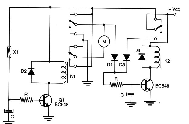
This application circuit, based in the article MEC055E, can be used in an intelligent robot. The circuit shown in Figure 1,

When activated by a sensor (as in the previous application), closes the relay, reversing the propulsion system.
But, at the same time, C2 charges by R2 until transistor Q1 becomes conductive, closing the second relay. At this moment, the power supply voltage is cut, and the entire system is stalled.
This configuration can be used to reverse the movement of a robot for a few seconds if it encounters an obstacle. Once it moves several centimeters away from the obstacle (to a secure position), it stops.
The values of R1, R2, C1, and C2, which determine the timing of the circuit, must be established experimentally to suit the application. The values given in the diagram are typical for applications powered from supplies of between 6 and 12 V.


