Note: this article is part of my book Handbook for Mechatronics.
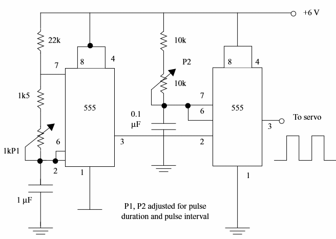
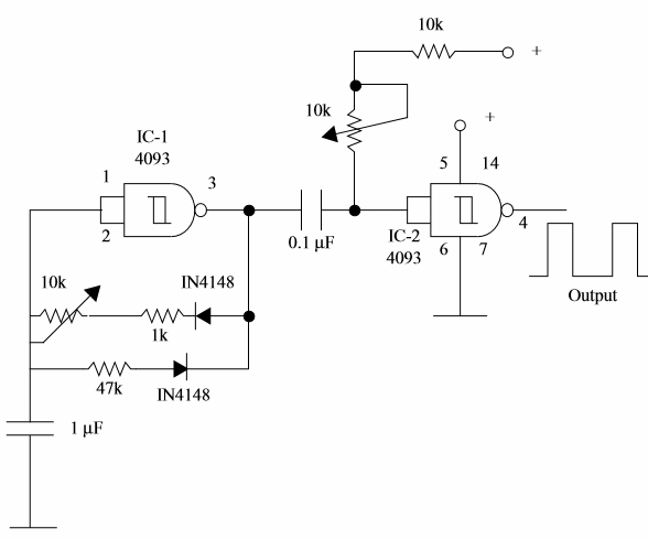
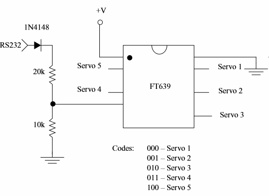
Figure 1 shows three circuits suitable for the control of servomotors.


(a) This circuit uses two IV 555 to generate the control pulses.
One of the ICs produces the delay and the other the pulse width. The delay (complete cycle) must be adjusted to 18 ms. The other circuit mist be adjusted according the position of the servo. A potentiometer or other resistive sensor can be usedin this cases.
Calibration can be made wiring an oscilloscope to the output of each IC (pin 3).
(b) This circuit uses two gates of a CMOS circuit
The time of the command cycle is produced by the oscillator formed by IC-1a. The trimmer potentiometer must be adjusted such way the circuit produce 18 ms pulses. This circuit commands IC-2a, a monostable with a time constant RC in the range between 1 and 2 ms. P1 is the control element that adjusts this time.
The components of the circuit must be be choosen to find the corrects times and frequencies ciompensating their tolerances. An oscilloscope is used to make the adjustments.
(c) Here a dedicated IC manufactured by Ferretronics (www.ferrettronics.com) is used - The FT639.
The FT639 is a servo controller chip. It will control up to five radio controlled servos through one 2400 baud serial line. No components are needed for a 0.5 V serial line as the ones found in microcontrollers like the Parallax Basic Stamp.
Each RC servo has 256 positions. To send the position of a servo to the FT639 two commands are needed: the first contains the servo number and lower 4 bits the positional number. The second comand the upper 4 bits of the posicional number. More information about the codes and the operation modes can be found in the site indicated above.
Testing a Servo Motor
To make tests of a servo motor at least some characteristics must be known as the power supply voltage or the type of control (pulses, voltage, current, etc). To test common RC servos, with voltages in the range from 4.8 to 6.0 V the next procedures are suitable.
You can find RC servos in toys, RC models as car and planes and use them to design a mechatronic device.
a) Electrical tests
Power the servo from a DC supply with voltage according the type and use circuits (a) or (b) - figure 2 to verify the positions of the shaft. If you have an oscilloscope you can determine the type of command necessary for a servo (length of pulses and cycle).
b) Mechanical Tests
The main mechanical test that can be made with a servo is the torque measurement.


