The purpose of this article is give suggestions about the use of mechanical switches, reed-switches and home made devices as sensors. Pairs of metal blades, common on-off switches, push-buttons, microswitches and reed-switches can be used as sensor in robots and mechatronics projects or in shields for microcontrollers.
A motor can be reversed when the robot stops in an obstacle or a mechanical arm beats against an object. A mobile robot can change its direction if a sensor detects a wall in its way. You can add mechanical sensors to your projects starting from some common components and configurations as the next:
On-off switches - microswitches
On-off switches can easily be adapted to be used as position sensors in many applications. Figure 1 shows how can we adapt a slide on-off switch (SPST) to be used as an impact detector.
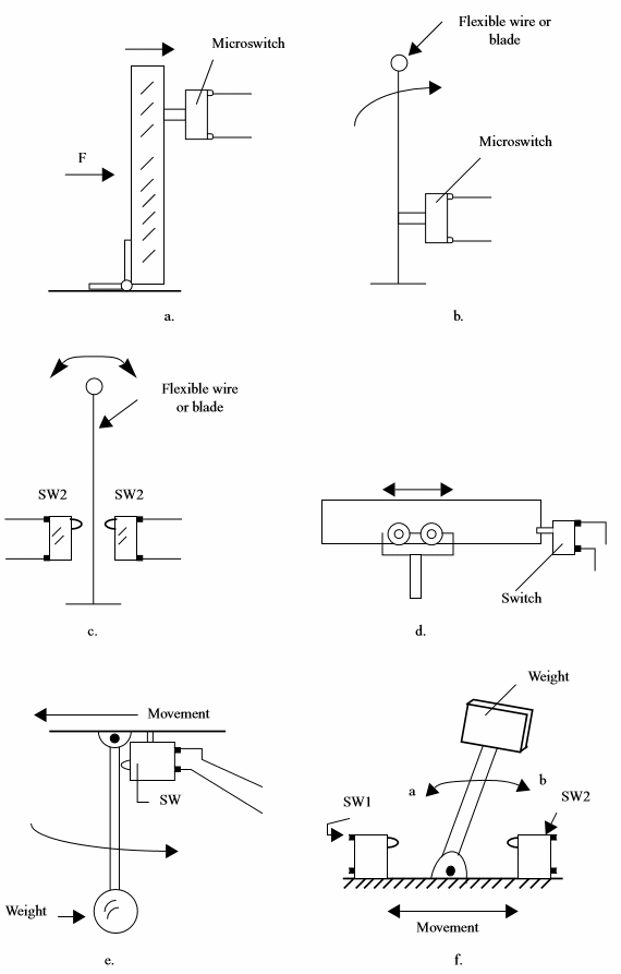
(a) Using a micro-switch as impact detector
(b) Position sensor using one microswitch
(c) Position sensor using two microswictches
(d) Limit switch
(e) Moviment sensor
(f) Aceleration/Brake sensor
In (a) the switch can be placed in front of a robot and used to detect when it beats against any obstacle. Soft types are ideal for this applications since it will not be necessary many power to close it. In (b), (c) and (d) we show other applications of switches as sensors both for robotics and industrial automation. (f) shows an interessing sensor activated by breaking or acceleration. Thissensor can be used to revert the direction of the motor of a robot ou other vehicle when suddenly it beats against an obstacle.
Micro-switches as the ones used in industrial machines are also ideal for applications involving position sensors as the ones shown by figure 2.
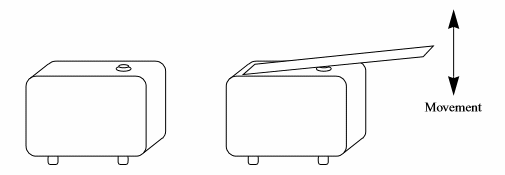
These switches are small and soft detecting needing a force applied to a mechanism. Many types of mechanisms can be adapted to common switches to convert them in sensors. Lervers can increase the sensivity of a microswitch.
Push buttons can also be used as sensors, as shown by figure 3.

It is important to choose one that can be easily closed with the mechanism you have.
Reed switches
Reed switches are devices formed by a glass enclosure filled with an inert gas and blades with electric contacts as shown by figure 4.
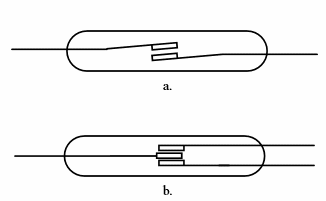
(a) SPST
(b) NC/NO switch
The presence of a magnetic field acts on the blades making them to touch one in the other and so close the circuit. Reed switches are very sensitive but can't operate with large currents. Typical currents are in the range between 50 mA and 500 mA. Since they can switch a circuit very fast, they can be used in high speed applications, sensing the rotation of a shaft or any mobile part of a mechanism.
Fixing a magnet in a wheel and placing a reed switch in an appropriated way it is possible to produce a pulse by revolution. The pulses can be used to control the speed of the wheel or to excite a tachometer circuit.
Figure 5 shows ow reed switches can be used as sensors.
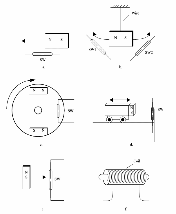
(a) Position sensor
(b) Inclination sensor
(c) RPM sensor
(d) Limit switch
(e) Proximity sensor
(f) Reed relay
Home-made sensors
Two or three blades placed togheter as shown by figure 6 form a mechanical sensor with many applications in robotics and mechatronics. The blades and the contacts can be found in old relays or switches. The reader only must take some care to see if the contacts are in good conditions of use.
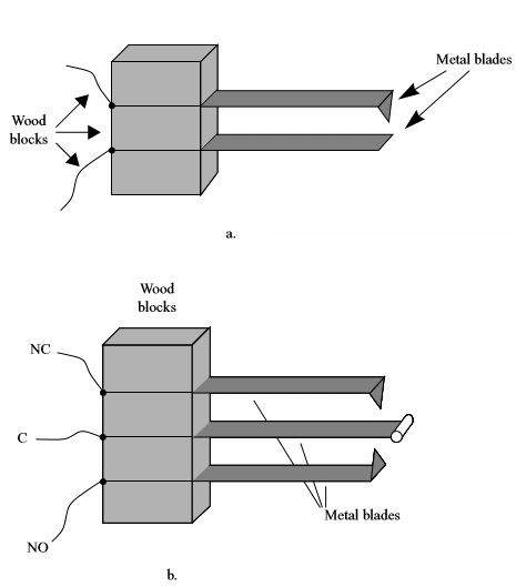
Dark contacts or deformed contacts indicates burns that affects the efficience of the sensor and it would be better not to use them.
The blades can be activated by many types of mechanisms. The figure shows some suggestions of mechanisms that can be used to act on this kind of sensor.
(a) Simple blade SPST switch as position sensor
(b) Three blade SPDT switch as position sensor
A long spindle, for instance, can be used for a position or obstacle sensor.
Contact Conditioners
When a switch is closed the electric contact isn' t stablished immediatelly.
Mechanical contacts as the one found in switches, relays and sensors produce noise during their setting time. They bounce and make repeated contact during the first milliseconds of action as shown by figure 7.
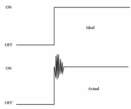
Logic circuits as TTL and CMOS and even other electronic circuits are fast enough to recognize each and every bounce or noise pulse as a separated impulse or logic level change. You close the switch one time, waiting for adding one count and the circuit will jump couting many comands.
To avoid this problem when using switches, reedswitches, relays or other on-off sensor with mechanical contacts a proper conditioning circuit must be used.
Figure 8 shows some debouncing configurations.
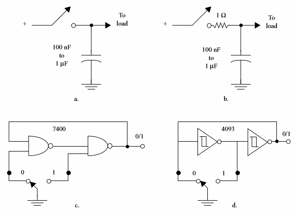
(a) Simplest debouncing circuit using a capacitor
(b) Circuit using a RC network
(c) Debouncing using TTL logic
(d) Deboucing using CMOS logic
Switches as sensors
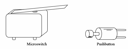
There are many types of switches that can be used as sensors or adapted to that task. Momentary switches can be used as bump sensors, navigation feelers and limit sensors. The most useful of the switches are the micro-switches and the push-button switches as the ones shown by figure 9.
Home-made sensors
Many home-made sensor can be mounted by the robotics and mechatronics builder.
Some home made sensor are shown in figure 10.
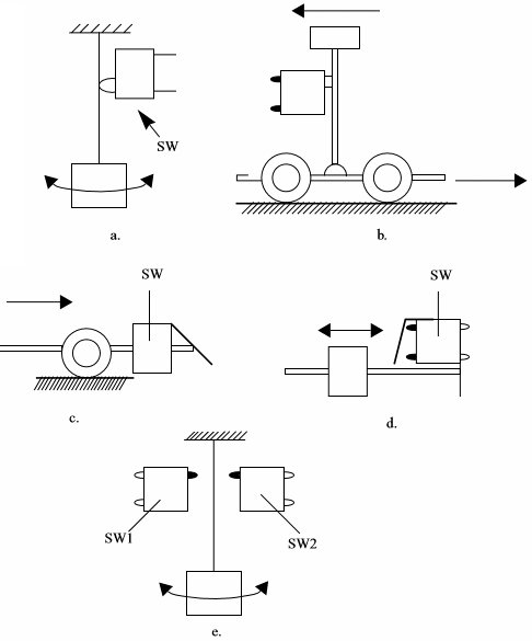
They are:
(a) inclination sensor
(b) aceleration sensor
(c) bump sensor
(d) limit sensor
(e) two-position sensor
Since these sensor can produce only short bursts of current when activated, appropriated circuits can be used as signal conditioners.
Programmed or sequential mechanical sensors
Simple arrangements using wheels and screws can result in position sensors or programmed sensors as the ones shown by figure 11.
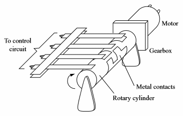
(a) a cilinder covered by a metal plate can be used as a position sensor. The array of blades touch the metal only in the points where no isolation is programmed. The designer can program the covered and uncovered positions of the cilinder according the signal to be produced by the switches.
TTL and CMOS Suitable for Contact Conditioners
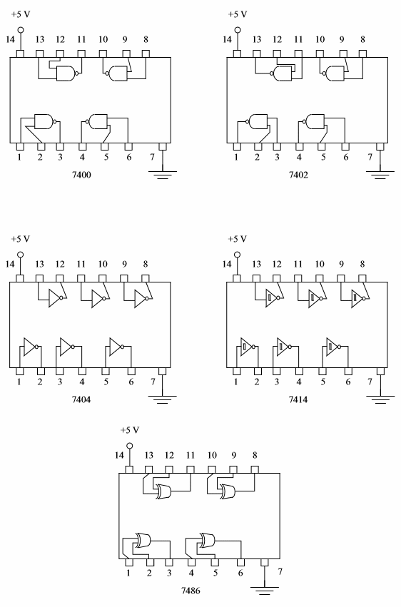
a) TTL Gates and Inverters that can be used in Contact Conditioner and Other Logic Applications
| Type | Function |
| 7400 | 4 2-input NAND Gate |
| 7402 | 4 2-input NOR Gate |
| 7404 | Hex Inverter |
| 7414 | Hex Schmitt Trigers - inverting |
| 7486 | 4 Exclusive-Or Gate |
Figure 12 shows the package and pinouts for these ICs.
Remember that:
Any regular TTL output can sink 16 mA but only source 0,4 mA
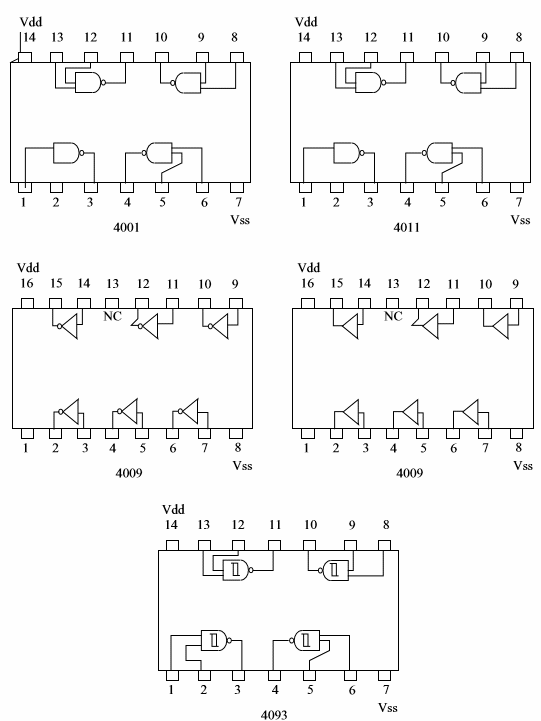
a) CMOS Gates
| Type | Function |
| 4001 | 4 2-input NOR Gate |
| 4011 | 4 2-input NAND Gate |
| 4009 | Hex Buffers (inverting) |
| 4010 | Hex Buffers (non inverting) |
| 4093 | 4 2-input NAND Schmitt Trigger |
Figure 13 shows the package for these ICs.
Remember that:
Any CMOS output can sink or source currents according the power supply voltage as given by the next table:
| Power Supply Voltage | Output Current (Sink or Source) - typ. |
| 5 V | 0.88 mA |
| 10 V | 2.25 mA |
| 15 V | 8.8 mA |


