A buoy which reaches a certain height in a tank, a door that opens, a scale that moves are some examples of devices that can be used to activate electronic circuits, through position sensors.
In the research lab, an object that shifts position in a controlled drop or even a scale or even animal-activated devices (guinea pigs) can be used to activate electronic recording, alarm or even feedback devices according to a program.
At home, the position of a door can be used to trigger an alarm and in industry the position of a part in a machine can be used to accuse a start or end of function or to trigger an alarm, detecting an abnormality.
These are just a few examples of devices which can be controlled by position sensors. (Figure 1)
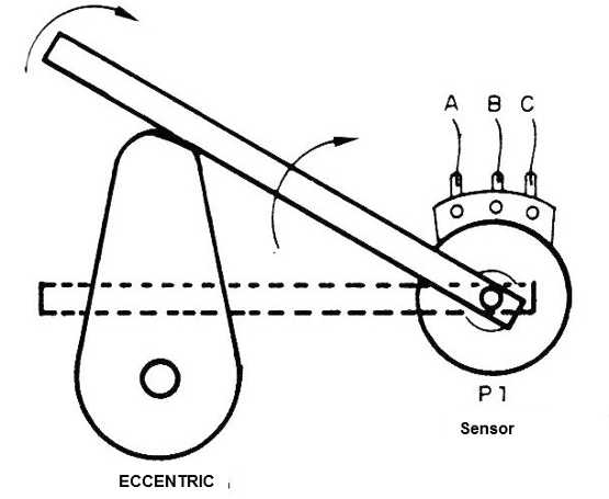
The three designs that we described in this article use common potentiometers as sensors.
These have the advantage that they can be easily coupled mechanically to the controlled systems and have good accuracy in determining the trigger points.
On the other hand, the use of a relay allows the controlled load to be electrically isolated from the sensor and trigger circuit which can be very important for safety reasons in many cases.
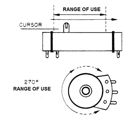
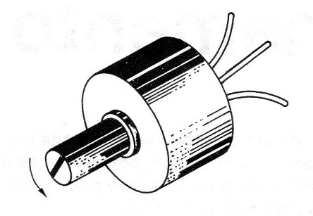
Because the potentiometers can be both rotating and sliding, the circuits can be used for linear displacement sensing (sliding pots) as well as for sensing movements or angular displacements (rotary potentiometers), as shown in Figure 2.
Our circuits have the following basic electrical characteristics:
FEATURES
Supply Voltages: 6 to 12 V
Relay contact: 6 amp/250 V
Sensor: potentiometer from 10 k ohms to 100 k ohms
Current consumption of the circuits: 2 to 20 mA (without energizing the relay)
HOW IT WORKS:
As position sensors we can use both common potentiometers or special resistive sensors, depending on the application and the desired precision.
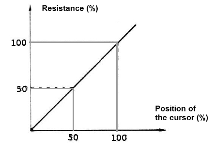
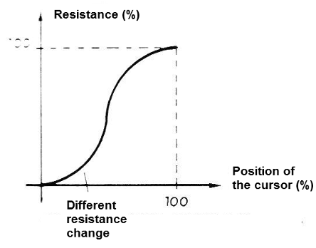
In a common potentiometer, the resistance shown between the slider and one of the ends depends on the angle of the slider in the rotary types or linear displacement for the sliders.
In linear types (lin), the relation is a direct proportion, as shown in the curve of Figure 3.
In logarithmic types, this curve is as shown in Figure 4.
The accuracy of a common potentiometer is small, but since the circuit has adjustments or means of compensating, this problem can be easily overcome unless an industrial sensor such as the one in Figure 5 is employed.
We give two types of circuit in this article:
The first type presented in two versions consists of a system which triggers a relay when the cursor reaches and surpasses a certain position.
In the first version there is a lock, which means that if the adjusted position is reached, the relay will trigger, it remains so indefinitely, even if the potentiometer returns to the position above the trigger point.
In the second version, it only remains triggered when the potentiometer is in the position above the trigger point. If the potentiometer or sensor returns to its original position, the relay disarms.
In the second circuit, we have the so-called "window" detector, where there is a determined range in which the relay stays activated, ranging between two positions of the cursor displacement, as shown in Figure 6.
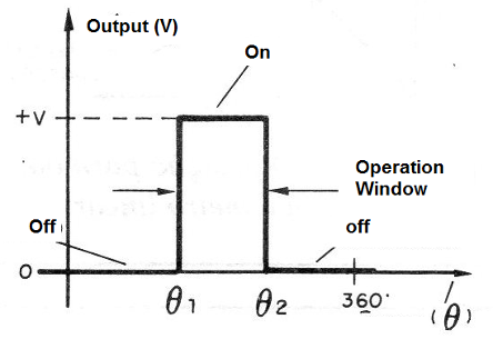
Below the lower limit and above the upper limit of the setting, the relay remains disarmed. In a fine tuning, the system can be used to detect a well-defined single position.
The width of the working range can be changed easily which guarantees a good margin of precision and also facilitates the adaptation of the circuit to the use for specific purposes.
CIRCUIT 1 - POSITION DETECTOR WITH LOCK
The circuit shown in Figure 7 triggers an SCR and consequently a relay when the position sensor (P1) reaches a certain position.
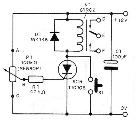
This circuit is provided with a lock, which means that even if the sensor returns to the original position, the relay remains activated in the non-trigger range. To deactivate, you must either turn off the power for a moment or press S1.
For a 12 V supply we use a G1RC2 relay, remembering that in the SCR we have a small voltage drop of the order of 2 V.
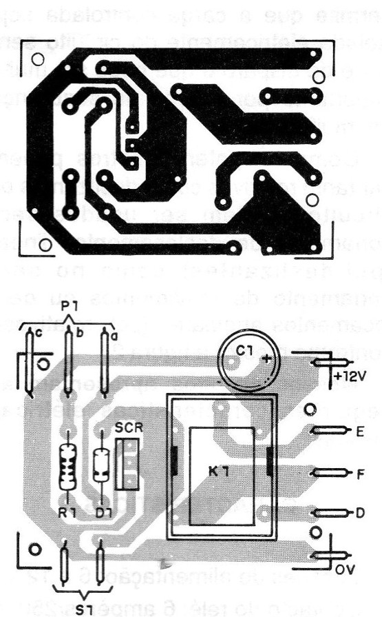
The arrangement of the components for this assembly on a small printed circuit board is shown in Figure 8.
The wires for the sensor connected to A, B and C can be very long and there is even the possibility of the third conductor (C) being replaced by a ground connection as shown in Figure 9.
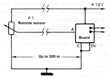
To use the appliance, position P1 so that the relay triggers at the desired position.
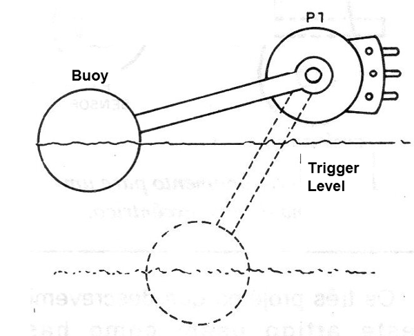
In Figure 10 we show a simple way of causing the circuit to trigger with the water level being exceeded in one place through a buoy coupled to the axis of a potentiometer.
SCR - TIC 106 - silicon controlled diode (B or D)
D1 - 1N4148 - general purpose diode
K1 - Economic relay of 12 V or equivalent
S1 - Pressure switch
P1 - 100 k ohm - sensor - see text
R1 - 47 k ohm - resistor - (yellow, violet, orange)
C1 - 100 uF X 16 V - electrolytic capacitor
Miscellaneous: printed circuit board, source, wires, welding, etc.
CIRCUIT 2 - POSITION DETECTOR WITHOUT LOCK
The circuit shown in Figure 11 triggers the relay whenever the sensor surpasses the balance position, turning it off when it is returned to normal the position.
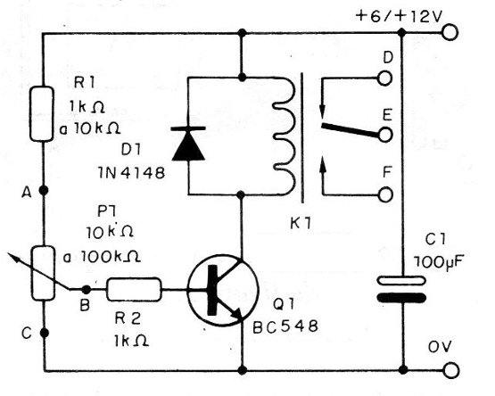
The relay allows the control of external loads up to 6 amps and the power can be made with voltages of 6 or 12 V depending on the relay coil used.
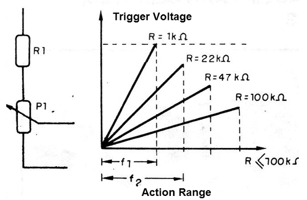
The choice of the value of the sensor and the resistor in series allows to adjust the range of the system.
With a potentiometer of 10 k ohms and a resistor of 10 k ohms or greater for R1, for example we can move the trigger range, as shown in Figure 12.
We observed that this circuit is endowed with a certain hysteresis, which means that the point that occurs the triggering in the sensor going to the region of the relay activation occurs after the point at which it gets turned off on the way back,as shown in Figure 13.
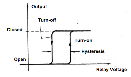
This is due to the mechanical and magnetic features of the relay.
The use of the potentiometers of great values tends to reduce this range, since the user must choose the values experimentally according to the application.
In Figure 14 we have the arrangement of the components on a printed circuit board.
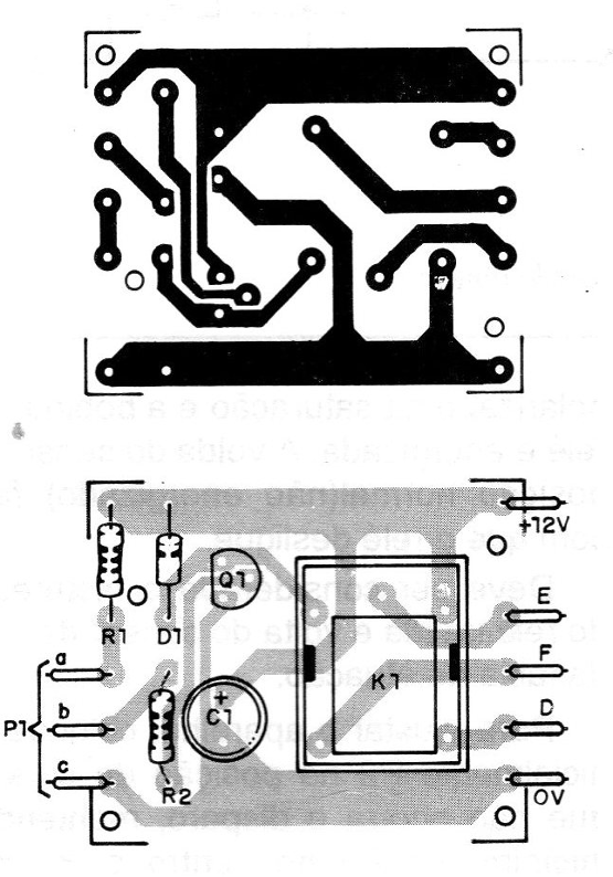
The sensor connected to points A, B and C can be connected by means of long wires. The C wire can be eliminated in favor of a good ground connection.
To use the device is simple: simply position the sensor so that the trigger occurs at the desired point.
Q1 - BC548 or equivalent - Generation NPN transistor
D1 - 1N4148 - silicon diode
K1 - 6 V or 12 V - relay
P1 - 10 k ohm at 100 k ohm - potentiometer (position sensor)
R1 - 1 k ohm at 10 k ohm - resistor (brown, black, red)
R2 - 1 k ohm - resistor (brown, black, red)
C1 - 100 uF x 16 V - electrolytic capacitor
Miscellaneous: printed circuit board, wires, power supply, welding, etc.
CIRCUIT 3 - POSITIONING DETECTOR WITH A WINDOW
The circuit of Figure 15 is a detector that operates in a given range, given by P2 and P3 settings as explained in the introduction of this article.
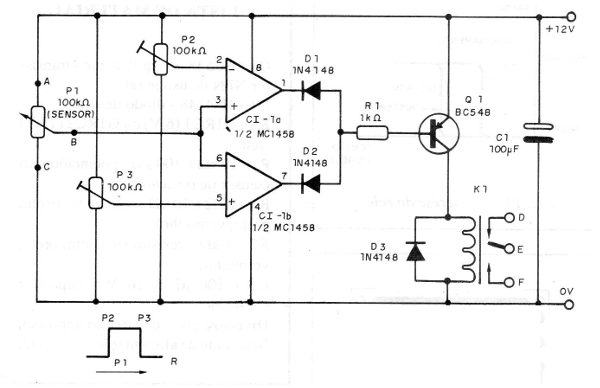
The circuit will keep the relay locked only within a range of sensor cursor positions.
Operational amplifier 1458 may be replaced by two independent operators such as 741 or even comparators of the type found in an LM139 or 339.
The arrangement of the components on a printed circuit board is shown in Figure 16.
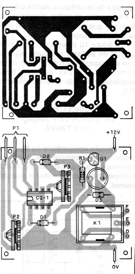
P2 determines the voltage reference for CI-1 a while P3 determines the voltage reference for Cl-1 b.
In the conditions of non-operation of the relay, (contacts open) the operational outputs remain at a high level.
The ranges are determined by P2 and P3 settings.
When either output is low, the transistor is polarized at saturation and the relay coil is energized.
Returning the sensor to the normal (non-energized) position causes the relay to shut down.
The relay hysteresis must be considered in the way back and forth of the sensor within the action range.
To set the device, initially set P2 to the non-triggered position of the cursor, initially holding P3 in the center and P1 also in the center.
Then push P1 to the position where the first trigger point is desired and set P3. Once this is done, move P1 to the second trigger position, thus setting the action range and P2.
The connection wire at P1 can be long and in this circuit the connection C can be eliminated by replacing a return via ground.
CI-1 - MC1458 - Dual Operational Amplifier
D1, D2 and D3 - 1N4148 - silicon diodes
K1 - 12 V relay
P1- 100 k ohm - sensor
P2 and P3 - 100 k ohm - potentiometers or trimpots
Q1 - BC548 or equivalent - NPN transistor
R1 - 1 k ohm - resistor - (brown, black, red)
C1 - 100 uF 16 V - electrolytic capacitor
Miscellaneous: socket for the integrated, circuit board


