Resistive sensors add sensory capabilities to any robotics, mechatronics, or artificial intelligence project. This chapter describes how resistive sensors operate and how they can be implemented. We will see how light dependent resistors (LDRs) and CdS cells can be used as light sensors, adding vision to robots and other projects. In addition, negative temperature coefficient (NTC) resistors can be used as temperature sensors, potentiometers as position sensors, and conductive foam as pressure sensors, adding tactile capabilities to robots and mechanic arms. Touch sensors are also described in this chapter.
Theory
The world around us is filled with variable physical conditions that change continuously. Temperature, air pressure, humidity, and light are some of the conditions that fill our living environment. Any sort of robot or mechatronic device that is intended to work in this environment must have some kind of resources that allow it to interact with it. Humans have built-in sensors such as ears, eyes, etc. But how can electronic devices interact with the world?
In robotics and mechatronics designs, we use transducers to interact with the external world. A transducer is a device that converts one form of energy into another. For instance, a photo cell used as a sensor can convert light level changes into electric signals. Another transducer device that can affect the ambient environment is the loudspeaker: it converts electrical energy into sound (mechanical energy).
To sense the world around them, robots and mechatronics devices can use many types of sensors. The next sections will describe some of them and describe blocks containing circuits that can be used with these sensors.
The LDR or CdS Cell
The light dependent resistor (LDR), cadmium sulfide (CdS) cell, or photoresistor is a component that changes its resistance with various levels of light. In the dark, the LDR presents a very high resistance—above 1 M?. This resistance will fall below 100 ? under direct sunlight. Figure 1 shows the appearance and the symbol used to represent an LDR.

The LDR is a resistor, so the current can flow in either direction. Although the LDR is very sensitive, “seeing” levels of light that our eyes can’t, the LDR is a slow device.
Fast light changes can’t be detected by an LDR. The upper limit of the frequency response of an LDR is around 10 kHz. If you need to detect faster light changes, you can use other sensors such as photodiodes and the phototransistors.
Using the LDR is very easy, since it can directly bias semiconductor devices such as transistors, SCRs, ICs, etc. LDRs can be used as “electronic eyes” in applications involving robotics, mechatronics, and artificial intelligence. As in the human eye, a lens can be added to enhance the performance of an LDR in a particular application. By placing a convergent lens in front of an LDR, we can pick up more light from one direction, increasing sensitivity and adding directivity.
LDRs can be found in different sizes and formats but, in general, their electrical characteristics do not differ much. This means that almost any type can be used in the blocks described in these pages.
Negative Temperature Coefficient Resistors
Negative temperature coefficient (NTC) resistors, also called thermistors or thermally sensitive resistors, are components whose resistance changes with temperature. The resistance of an NTC falls as temperature increases.
Another temperature-sensitive device is the positive temperature coefficient (PTC) resistor. In this component, resistance increases with temperature. Figure 2 shows the symbol and appearance of common NTCs.
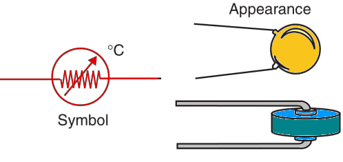
NTCs can be used to add temperature sensing to robots and other projects. They are specified by the resistance (in ohms) they have at a particular temperature (normally, the ambient temperature, or 20°C). Values are typically in the range from several ohms to 100 k?.
Temperature sensors such as the NTCs are not fast. They can’t change resistance to match fast changes in temperature. This is because they have to change their own temperature, dissipating heat into the ambient, or drawing heat from it, until they reach ambient. The speed of the heat changes is basically determined by the size and the material of the NTC. Small NTCs are faster than larger ones and can better sense fast changes in ambient temperature. Because the electrical characteristics of NTCs (and PTCs) are the same as those of LDRs, they can be used with the same circuits or blocks.
Pressure Sensors
Simple pressure sensors can be made using conductive foam such as the materials used to protect ICs against electrostatic discharge. Figure 3 shows how an IC is protected by the foam and how it can be used for our purposes.
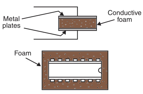
Placing the foam between two metal plates as shown in the figure, you create a pressure sensor. If you press the plates together, the resistance of the foam changes (decreases), and this can be used to trigger a circuit. You can use this kind of sensor with the same block recommended for LDRs and NTCs.
Potentiometers as Position Sensors
Common potentiometers can be adapted to function as position sensors. You just need to couple some kind of mechanical device (a lever or a wheel) to the shaft of a rotary potentiometer to derive an electric signal from the position of the device. Figure 4 shows how a rotary potentiometer can be used as a position sensor. Potentiometers with values in the range of 10 to 100 k? can be used as position sensors with all the blocks suggested for the other resistive sensors and described in this part.
Slide potentiometers can also be used as sensitive position sensors, as shown in Figure 5. See other articles in this site, for examples of how a potentiometer can be used to sense the position of the shaft in a gearbox.
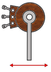
Figure 5 – lide pot used as position sensor
Touch Sensors
Two plates in close proximity, but not touching, form a touch sensor. If you place your fingers on the two plates so that you touch both at the same time, as shown in Figure 10.6, an electric current can flow across your skin, creating an electrical signal. Since the resistance of your skin is very high (100,000 ? or more), the current flowing by this sensor isn’t enough to drive common circuits. Amplification stages are needed.
An important point is that we must keep the current low; if high voltage is used in this sensor to increase the current, electrical shock may result.
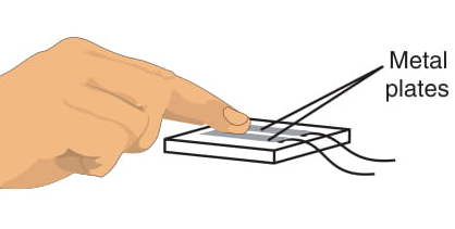
In summary, the main characteristic of touch sensors such as the ones described above is that they must operate in isolation from the ac power line and have current limit resistors. Another type of touch sensor is the one shown by Figure 7. If one plate is removed and connected to ground, one need only touch the other plate to trigger the circuit. The current will flow across the body of a person, activating the circuit.
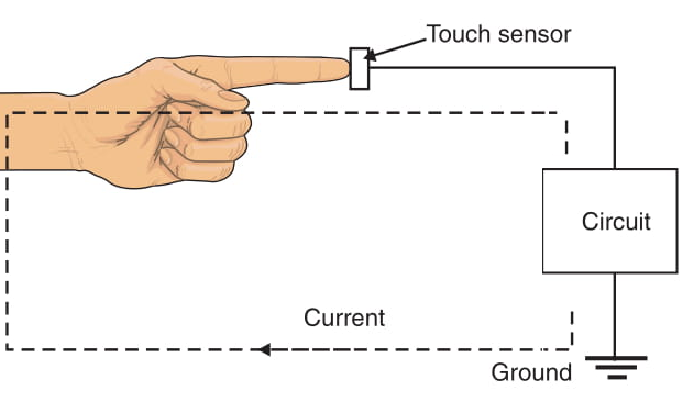
How to Use Resistive Sensors
When using resistive sensors, the designer must keep in mind some important questions.
1. How much does the resistance change under the desired operating conditions?
The resistance range of a sensor is important in the design or choice of the circuit. If a sensor changes by only few ohms resistance when excited, the circuit must have special characteristics to react to this small change. LDRs change resistance over a large range of values, so they are easy to use. NTCs, depending on the type, also have a wide resistance range, but others (e.g., pressure sensors do not).
2. Is the current provided by the sensor enough to drive a circuit?
If the sensor have a large resistance drop when excited, the current can be enough to drive any of our circuits. In general, to drive a block with a bipolar transistor, the resistance in the low-value condition must be less than 50,000 Ω. If Darlington transistors, CMOS ICs, or two-stage circuits are used, this resistance can be higher—in the range of 200,000 to 1,000,000 Ω. As a general rule, if your sensor doesn’t trigger the circuit, try another block with higher sensitivity.


