The transformer used in this design has voltage and current according to the controlled motor. The indicated transistor is for currents up to 1 A safely, but we can use other Darlingtons for larger currents.
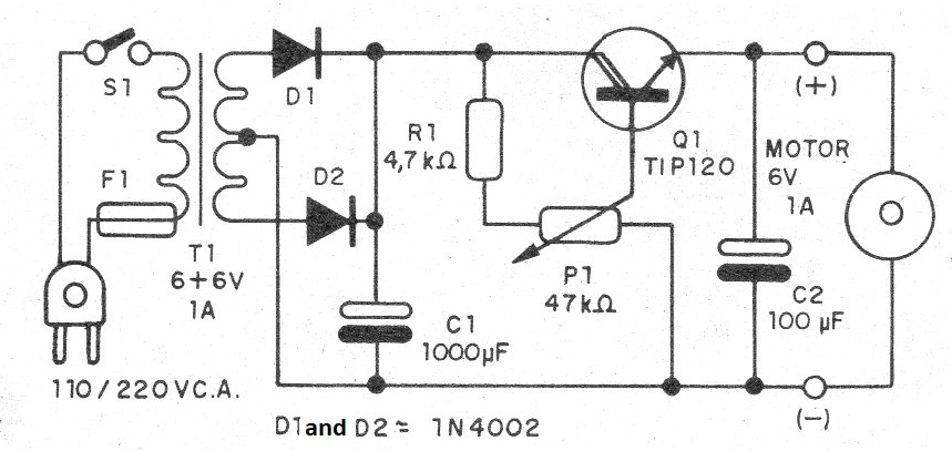
This component must be equipped with a heatsink and for currents in the indicated values the diodes may be 1N4002 or 1N4004. The original design was designed to control gearboxes which trigger light effects with mirror globes, but any mechatronic application can be included. In Figure 1, we have the complete control diagram.
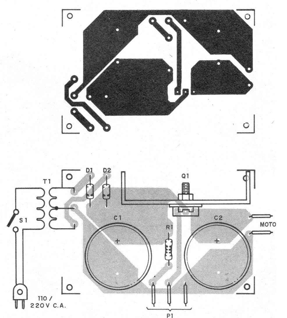
The printed circuit board for the control is shown in Figure 2.
The resistor is 1/8 W and the C1 electrolytic capacitor must have a working voltage greater than the transformer secondary peak, for example 25 V for a 12 V transformer.
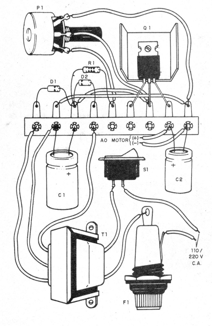
C2 may have lower voltage according to motor. A terminal strip assembly as a lower cost option is shown in Figure 3.
Q1 - TIP120 - Darlington NPN Power Transistor
D1, D2 - 1N4002 or 1N4004 - Silicon Diodes
T1 - 6 to 12 V secondary transformer, 500 mA to 1 A, depending on the motor
R1 - 4k7 ohms - resistor - yellow, violet, red
P1 - 47 k ohms - Potentiometer
C1 - 1000 uF - electrolytic capacitor
C2 - 100 uF - Electrolytic Capacitor
F1 - 1 A- fuse
Miscellaneous:
Terminal strip or printed circuit board, power cable, fuse holder, wires, welding, etc.


