Integrated circuits which form a microcontroller board, such as the Arduino, are extremely delicate and any higher voltage pulse can cause immediate and irreparable damage.
On the other hand, circuits controlled primarily in hostile or grid-connected environments in robotics and mechatronics experiments usually involve the use of inductive loads such as motors, solenoids, and relays which are devices that, in addition to operating at high voltages, are responsible by the production of high voltage pulses when they switch.
How do we isolate the two devices without, however, losing the information that should be transferred?
Physical means, such as circuits, even provided with protective elements are not very safe, and should be avoided. This means that the use of direct connections is not recommended.
This leads to a solution adopted almost entirely on all digital interfaces or shields: the use of optical coupling.
THE OPTICAL COUPLER
An optical coupler is formed of a light source which can be modulated or easily controlled such as, for example, an infrared LED and a receiver that can receive and produce a signal from the modulated light signal.
The two elements are built in a hermetic chamber without physical contact, as shown in Figure 1.
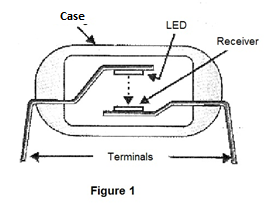
This physical separation, while not impeding the passage of the signal from one to another in the form of electromagnetic radiation, provides insulation of thousands of volts between the circuits of the two components.
Designers of interface circuits or shields can rely on a large number of couplers which basically differ from the type of receiver device used.
The type of signal to be transferred from the control circuit (Arduino, for example) to the controlled circuit (external load) will determine the features of this element.
Thereafter we will address several types of couplers which can be used in interfacing with their typical circuits.
a) COUPLERS WITH PHOTOTRANSISTORS
These are the most common since the signals obtained at their output can be regain their original form.
In Figure 2, we have the symbol used for a coupler of this type in which we have an infrared emitter LED as a transmitter and a phototransistor (which can be simple or Darlington, depending on the type) which receives the signals.
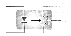
The LED is connected to the digital output of an Arduino, for example 3.3 or 5 V which provides the driving signal. The resistor used in this type of coupling is usually from 330 ohms for 5 V and 220 or 330 ohms for 3.3 V.
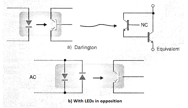
Variations for this type of coupler include types with photo-Darlington transistors and types with opposing LEDs that can work with alternating signals. These types of couplers have their symbols shown in Figure 3.
With the use of an amplifier stage, with one or more transistors, it is possible to directly drive a relay or another type of load with this type of coupling, as shown in Figure 4.
In table 1, we give a list of optical couplers with transistors with their features.
Table 1
| Tipo | Isolamento | V(BR)CEO (*) |
| TIL111 | 1500 V | 30 V |
| TIL112 | 1500 V | 20 V |
| TIL114 | 2500 V | 30 V |
| TIL115 | 2500 V | 20 V |
| TIL116 | 1500 V | 30 V |
| TIL117 | 1500 V | 30 V |
| 4N25,A | 2500 V | 30 V |
| 4N26 | 1500 V | 30 V |
| 4N27 | 1500 V | 30 V |
| 4N35 | 3500 V | 30 V |
| 4N36 | 2500 V | 30 V |
| 4N37 | 1500 V | 30 V |
| H11A2 | 1500 V | 30 V |
| H11AV3 | 7500 V | 70 V |
| MCT275 | 3000 V | 80 V |
One of the most popular components of this family, which can be easily found, is the 4N25 whose pinout is shown in Figure 5.
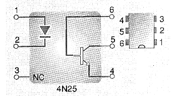
This component has an insulation voltage of 7,500 volts and is presented in a 6 pin DIP enclosure.
In Figure 6, we have an application circuit for the 4N25 with an external amplifier which can be used to drive power loads or a relay.
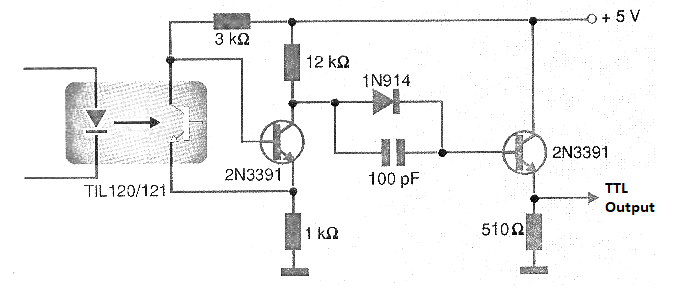
Circuits suggested by Texas Instruments using TIP102/103 or TIL120 or TIL121 are shown in Figure 7.
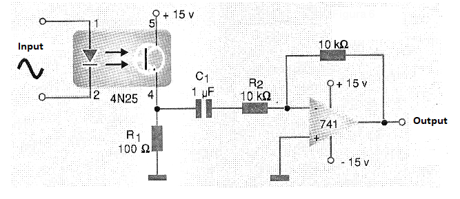
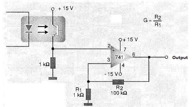
Figure 8 shows the use of an operational amplifier 741 type along with an optical coupler in order to obtain a higher intensity signal for external driving. This circuit should be powered with a symmetrical 15 volt source.
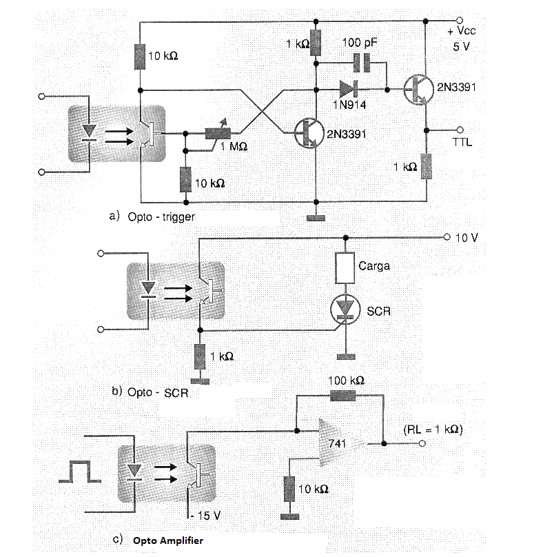
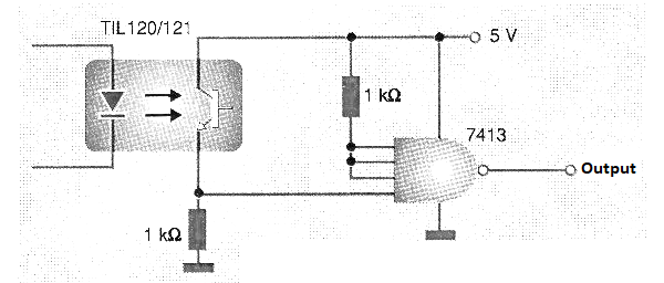
The interfacing with TTL circuits is shown in Figure 9.
In table 2, we give a list of optical couplers with Darlington transistors.
| MOC3009 | 250 V | 30 mA |
| MOC3010 | 250 V | 15 mA |
| MOC3011 | 250 V | 10 mA |
| MOC3012 | 250 V | 5 mA |
| MOC3020 | 400 V | 30 mA |
| MOC3021 | 400 V | 15 mA |
| MOC3021 | 400 V | 10 mA |
| MOC3023 | 400 V | 5 mA |
Isolation voltage – 7500 V for all
As we can see, the insulation voltages are also high. The advantage of this system is the possibility of having a higher intensity signal at the output, with less amplification steps to drive the controlled devices.
A Darlington phototransistor circuit is shown in Figure 10.
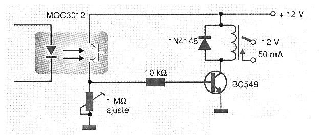
The resistor used as the load for the transistor (R1) can vary greatly depending on the supply voltage used and the gain of the transistor used in the next stage. The value shown in the diagram is typical.
OPTO TRIGGERS
An important series of couplers, which can be used in interfacing PCs with power loads, is the one that allows direct control of the triacs.
The Motorola MOC series has two very important components in this series which are the MOC3010 for triacs trigger at the 110 V network and the MOC3020 for trigger at the 220 V network.
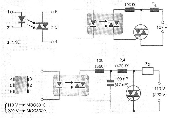
The pinning of these two integrated circuits is shown in Figure 11.
With typical insulation voltages of 7500 volts the two devices provide security to the PC circuit regarding the controlled circuits.
The MOC3020 is actually the first in a series which has MOC3021, 3022 and 3023 couplers as the additional elements. The main difference between the types is that the latter in the series need smaller currents in the LED to trigger. In an interface application, this is important given the limitation of the current available in the parallel outputs.
Thus we have the following typical trigger currents:
MOC3020 = 30 mA
MOC3021 = 15 mA
MOC3022 = 10 mA
MOC3023 = 5 mA
These values shown in the table are important for the correct dimensioning of the resistor in series with the LED.
OUTPUTS WITH SCHMITT TRIGGERS
The outputs with Schmitt Triggers are interesting when coupling the PC to a digital control circuit which requires transient free signals with very fast rise and fall in voltage.
For this purpose, we have devices such as Motorola's MOC5007, MOC5008 and MOC5009, whose pinout is shown in Figure 12.
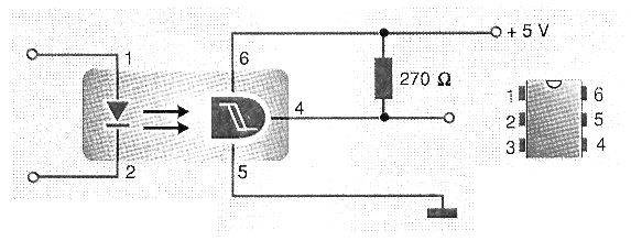
As we can see, these circuits contain a receiver with a very strong hysteresis feature with full compatibility with external TTL and CMOS circuits.
What differentiates the three types in the series is the intensity of the current in the LED which causes the trigger of the circuit, varying between 1.6 mA for MOC5007 and 10 mA for the MOC5009 (max).
This allows to increase the values of the resistors in series for driving. We can use 1k for 5V and 680 ohms for 3.3V in the case of Arduino.
Building of Shields and Interfaces
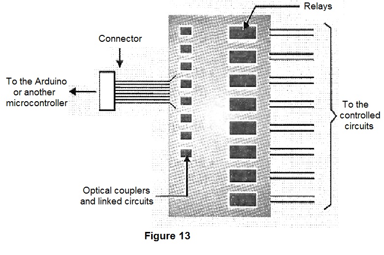
Taking advantage of the basic circuits and the indicated components, it is easy to design a control interface or shield with opto-isolators or optical couplers.
Simply repeat on a circuit board any of the circuits shown or even mix them according to the application and control them by the number of outputs of the Arduino or other microcontrollers, as suggested in Figure 13.
The main points to be considered in the design are the correct dimensioning of the limiting resistors of the gates and the separation of the tracks of the circuit board controlled from the control circuit.
The source for the controlled circuit should also be well planned so that there are no problems of high currents intensity in narrow tracks.

