
Note: The article was published in Mecatrônica Fácil magazine - a Brazilian magazine - in 2003 and reproduced here with the author’s permission.
The circuit of the "Insect Robot" can be seen in Figure 1. As the reader can see, we use the well-known Basic Step 1 microcontroller, which is also the target of a series of articles in this Magazine.
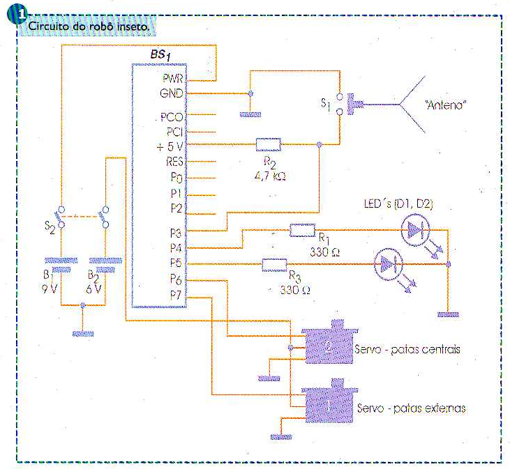
Basic Step I performs all the processing, controlling two common servos for model aircrafts, an "antenna" switch (sensor) and two LEDs (visual complements). One of the servos controls the "outer" legs and the other servo controls the "central" legs. The antenna works as a contact sensor and allows the "Insect Robot" to recognize obstacles and avoid them. In Figure 2, the reader will be able to better understand how the insect robot "walks".
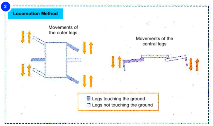
Analyzing this figure, the reader realizes that servo "2" acts by lifting one side of the insect robot (central legs). This causes two "outer" legs to be in contact with the ground and two not. The two legs in contact with the ground are controlled by servo “1” (external legs), which makes them move forward and backward.
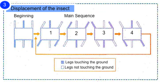
Figure 3 shows the sequence of movements of the insect robot. Raising one side (movements 1 and 2) and moving the "outer" legs, and then lifting the other side and moving the "outer" legs again (movements 3 and 4), we have the forward movement. Inverting this sequence, we have the opposite movement (backwards).
When the robot "detects" an obstacle through its sensor antenna, it prepares the detour. First it performs 4 steps backwards and then turns to the left side. However, it is necessary to talk a little more about the deviation so that the reader can better understand how it is done. Follow Figure 4.
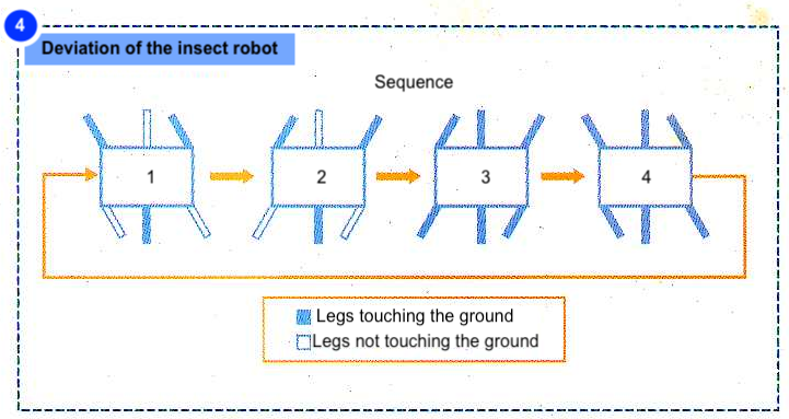
In some models of insect robots with a greater number of servos, the deviation becomes an easier task. In the case of the proposed robot, the detour is a little more complex. First, the robot needs to be "elevated" on one side. Then it needs to be moved backwards (movements 1 and 2). After this movement, the robot will have a slight tilt to the side. Then, we center the lifting legs and move the "outer" legs back to the opposite side (movements 3 and 4). At this moment, the robot is skating, since all the legs are in contact with the ground. Again the operation is performed until the movement is enough for the deviation.
ASSEMBLY
We divided the assembly of our insect robot into two parts: electronic and mechanical. We will use tools such as soldering iron, drill, stylus, etc. If the reader does not have experience with some of the tools to be used, it is recommended to ask for help from someone more experienced. Avoid accidents at all costs!
ELECTRONIC ASSEMBLY
The reader may choose to use a standard board or use the "layout", available for download on the magazine's website (not avaliable) to assemble the board which will contain the components. The board does not allow recording the Basic Step. This operation must be done outside the board.
The size of the board was dimensioned to be exactly the size of the insect robot base. Take great care when welding the LEDs, as these components are polarized. For mounting the Basic Step, the use of a support is highly recommended. This can be built from a 28-pin IC socket, using only one side. The servos can be soldered directly on the board, however the use of an "in line pin" type terminal will avoid cutting their terminals.
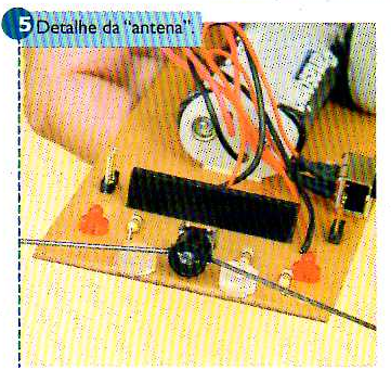
The "antenna" switch was assembled from a mini "push-button" and a piece of steel wire of 34 cm long and 2 mm thick. To hold the wire, we use a piece of plastic with a hole in the middle attached to the movable point of the button (key). We also used two small pieces of "hot glue", cut with a stylus, to give better support to the set. Look at Figure 5.
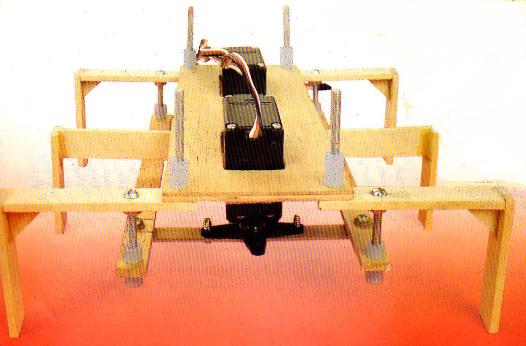
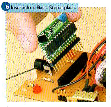
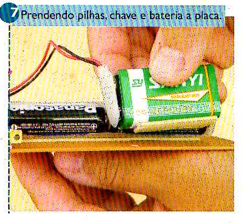
Insert Basic Step I into the board (Figure 6). Be careful not to put it inverted! To secure the battery holder, power switch and the battery to the board, the reader can use double-sided tape, hot glue, wire or the material that best suits you. In our prototype, we use double-sided tape. See Figure 7.
MECHANICAL ASSEMBLY
For the mechanical assembly, you will need some wood scraps and screws. In the list of components, the reader will be able to see the list required for this.
The robot base was mounted on 4 mm thick plywood. The holes are for ordinary model aircraft servos. Servo "1", which controls the "outer" legs, is in the front, and servo "2", which controls the "central" legs, is behind. Four small pieces of wood, 20 mm long and 5 square mm, were used to support the servos and allow them to stay at the correct operating height. Other four pieces of wood, 15 mm long and 5 square mm, were used to build the support of the central legs. All holes in the base are 1/8 inch in diameter. For gluing the pieces, preferably use the epoxy type glue for better mechanical resistance. In the absence of this type of glue, white glue or cyanoacrylate can be used.
LEG CONSTRUCTION
We need 4 outer legs and 2 central legs. These were made of wood, 3 mm thick and 12 mm width. All the holes in the legs are 1/8 inch in diameter, except those which should be drilled in the central legs for fixing the control wires, which must be the thickness of the wire to be used. Here, it is also recommended to use epoxy glue for better mechanical resistance.
CONSTRUCTION OF THE “TRANSMISSION” ELEMENTS
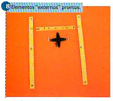
We call "transmission" elements all the elements necessary to transfer the movements of the servos to the legs. Two 175 x 10 x 3 mm pieces of wood (length, width and thickness) were used to connect the front and rear "outer" legs and a 93 x 10 x 3 mm piece of wood (length, width and thickness) to connect servo “1” to the "outer" legs. This last element must be screwed on a servo link, usually provided with it. In Figure 8, the reader can see them ready.
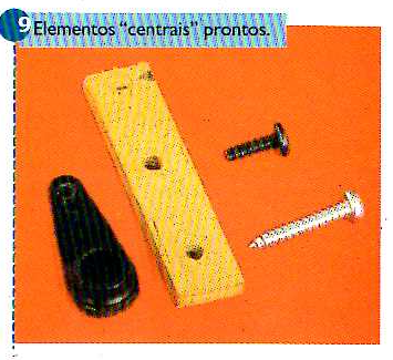
For the central element was used: 1 piece of wood 40 x 10 x 3 mm (length, width and thickness) which must also be screwed into a servo link and 2 pieces of steel wire with 2 mm thickness. The reader will be able to replace the wires with model aircraft parts known as ball link and threaded wire.
In our prototype, although we show in our diagram the design of the two wires, we used a wire for transmitting the movement and a set of parts from model aircrafts (2 ball links and threaded wire). We hope to demonstrate the use of various types of components and the various possible options in a single assembly. The finished parts can be seen in Figure 9.
ASSEMBLY
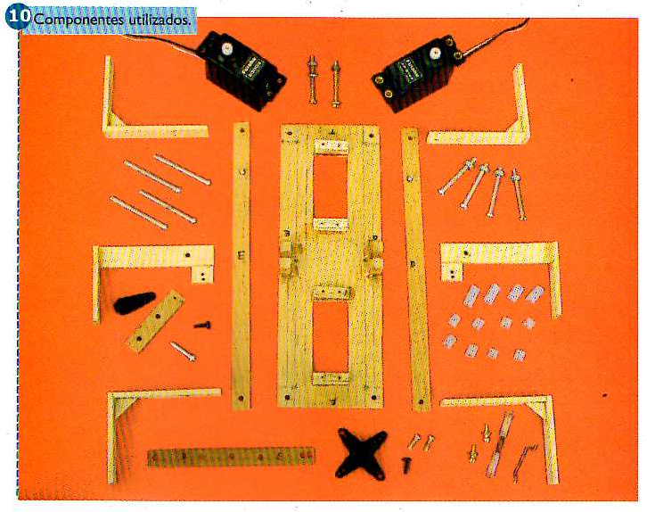
In Figure 10, we can see all the components used in this assembly. We remind you once again that in the list of components the reader will find the list of material needed for this assembly.
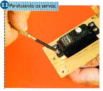
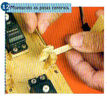
Begin the final assembly by screwing the servos (Figure 11). Then use screws to secure the center legs. At this point, it is highly recommended to use metallic washers between the central legs and the wooden support. This will help to reduce friction between the parts. See Figure 12.
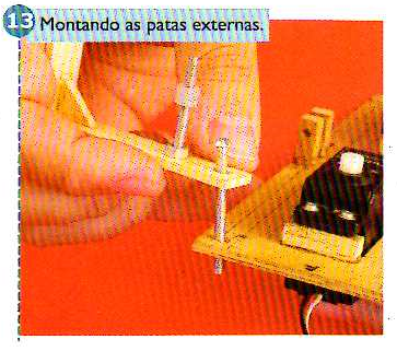
Then, you will be able to attach the "outer" legs. Remember to attach the screws first which will work as a support point for the external control elements. These screws are secured with nuts and must be tight. They face down.
To assembly the legs to the base, we will also use screws. However, these will face upwards and will later be fixed with the help of a piece of silicone, rubber or even plastic hose and will also work to support the control board (see Figure 13). The use of washers between the base and the outer legs is also recommended to facilitate the movements.
The "hose" must have its internal diameter smaller than the diameter of the screws used to fasten under pressure. It can be easily found in model shops, aquarium stores, pharmacies, etc. These lengths of hose must have it calculated so that they also allow the board to be supported without touching the servos.
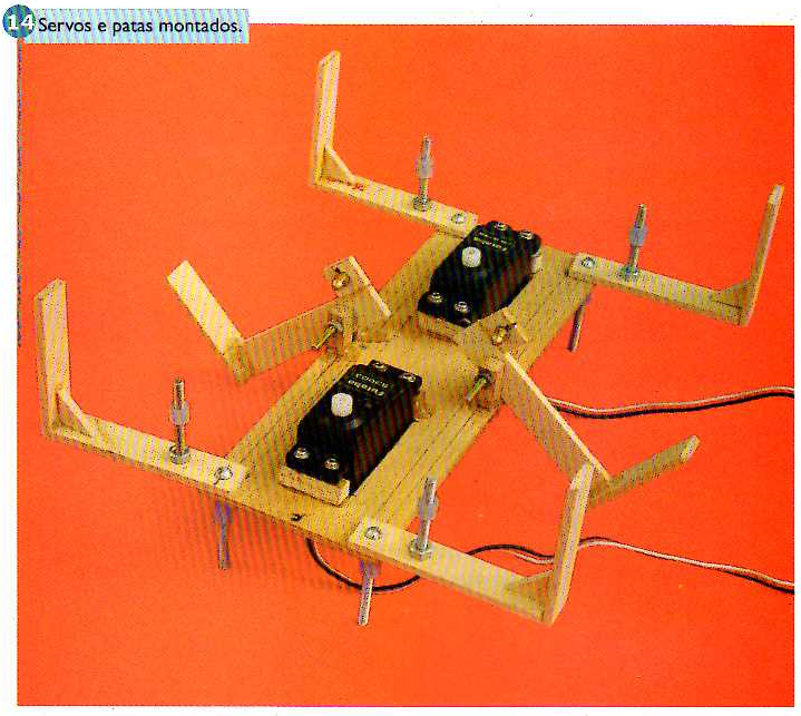
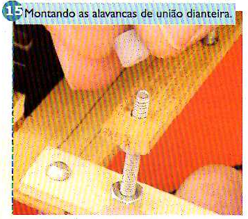
After assembling the servos and legs, our robot will have the appearance of Figure 14. Now we will assemble the levers which will join the "external" legs: front and rear. The transfer of movement is obtained thanks to a screw that should be attached in the hole to the center of each piece. To fix these parts to the robot, we will use small pieces of hose (already detailed), as can be seen in Figure 15.
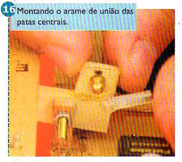
Then, we will assemble the central leg transmission set. The reader must have noticed that the central legs are joined together by a wire, which can be constructed, or by a set formed by 2 "ball links" and a piece of threaded wire (in fact only the threaded piece). The choice is up to the reader. In Figure 16, the reader can verify the assembly of the connecting "wire" between the central legs.
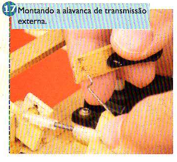
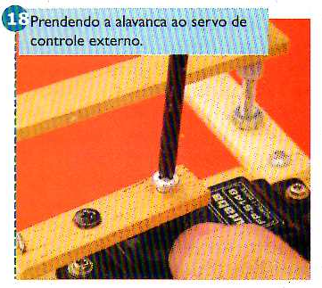
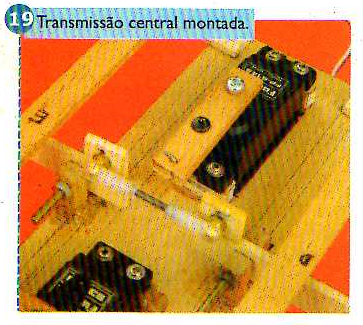
From this moment on, we need to unite the control servos to the legs through the control and transfer levers (transmission set). We will start with the central servo. We will connect the lever mounted for this to the legs with a wire that will transfer the movement to them, as shown in Figure 17. Attach the lever to the servo with a screw (Figure 18). In Figure 19, the reader has a detail of this set properly assembled.
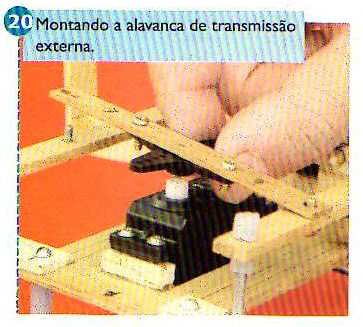
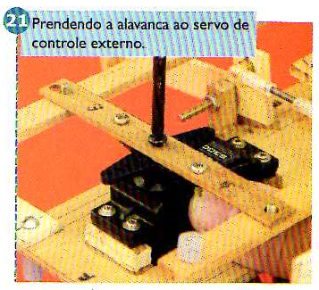
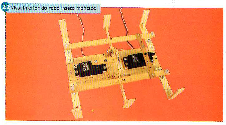
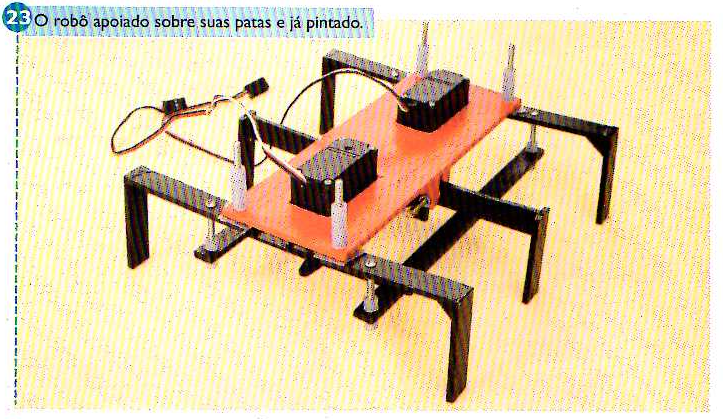
Now, we will attach the external movement lever to the front and rear transmission levers (Figure 20). Secure the lever to the servo with a screw (Figure 21). In Figure 22, the reader has a view of the bottom of the set properly assembled and, in Figure 23, we have the robot supported on its legs properly painted.
It is important for the success of this assembly that the screws and hoses used do not put excessive pressure on the legs. Thus, we prevent the servos from being overloaded during their operation. Keep in mind that it is necessary for the parts to be firm, but not to exert pressure between them.
MERGING THE MECHANICAL AND THE ELECtrONIC PARTS
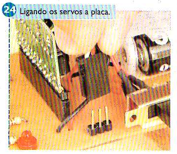
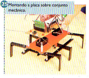
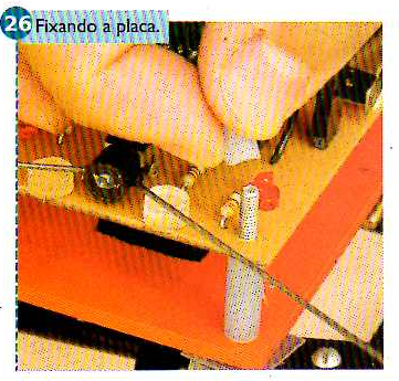
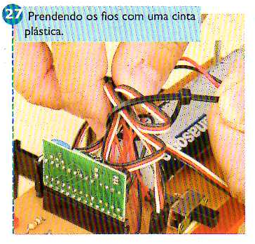
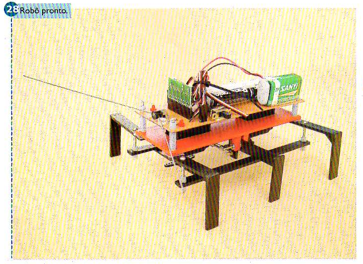
We can now unite the mechanical and electronic parts. For this, we need to connect the servos to the board, as shown in Figure 24. After that, we insert the control board to our mechanical assembly (Figure 25), fixing it with small pieces of silicone hose (Figure 26). The wires can be secured with the use of a plastic strap for a better finish and to prevent them from getting tangled in obstacles and/or in the robot's own "legs". See Figure 27 and Figure 28.
TEST AND USE
The Insect Robot board does not allow recording the Basic Step. This operation must be done on the Step Lab Board or on a "ready board", according to what is already done by the readers when using Basic Step on their bench.
With our robot ready and assembled, we can now proceed with our tests. Program Basic Step with and insert it again on the board. Turn on the switch S2 (cell batteries and battery must be installed). This small program only works to centralize the servos. This will assist in their correct positioning. The "legs'' of the robot, both external and central, must be centralized. The outer legs should be neither in front nor behind on either side. Both central legs should rest on the ground. Make all necessary adjustments.
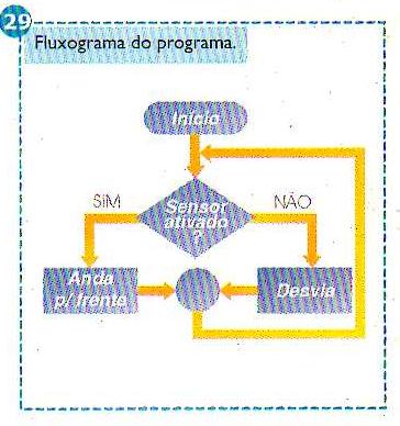
Once adjustments have been made, use the source code 2 (also available on the magazine's website) to program Basic Step. This source code contains the necessary programming for the movement of the insect robot. When turning on the robot, it must "walk" forward. When encountering an obstacle, it will make the detour, already commented earlier on this article. In Figure 29, the reader has a flowchart which allows understanding the functioning of the proposed program.
It is important to note that this robot was developed to move on smooth floors. It is not recommended to use it on rough floors and carpets. The effort on servos and mechanical parts will be excessive, and their displacement may be inaccurate and unsatisfactory.
Although the author used wood in his prototype, the reader can build the insect robot with several other types of materials such as plastic, acrylic, etc. The proposed measures may also be adapted according to the material to be used. The reader should only keep in mind that the lightness of the set is important for the project to be successful.
CONCLUSION
This little robot is sure to arouse interest and attention at a science and / or technology fair. The possible demonstrations are many and the use of other sensors and finishes can create diverse and very interesting "creatures". Everything is a matter of imagination. Have a good assembly!


