There are several ways to check the operation of an oscillator, depending only on the resources available in each workbench.
To facilitate the understanding of the test procedures, it will be interesting to divide the oscillators into two groups: low-frequency or audio oscillators and high frequency or RF oscillators.
As analysis resources of these oscillators there are the following possibilities:
Buzzers or, crystal or piezoelectric earphones
Multimeter
Proof amplifier or signal follower
AM, FM radio receiver
Pilot light
With these tools it will be easy to discover problems in oscillator circuits of several types.
Audio Oscillators
We can say that the audio or low frequency oscillators are those which produce signals in the audible range of approximately 15 Hz to 15 000 Hz.
These oscillators are typically used in applications where we want to have some kind of sound reproduced through a transducer or speaker.
The best way to know if an oscillator of this type is working is to withdraw the signal of some appropriate spot and amplifying it or applying it to a transducer check for sound reproduction.
For an oscillator with transistors, as shown in Figure 1 we can check the presence of signals at several spots.
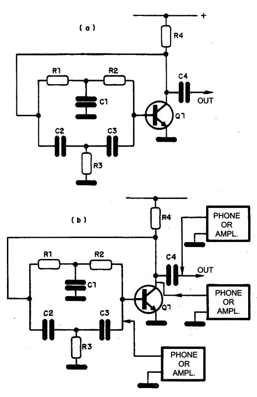
It is necessary to be careful so that the oscillator does not stop with the connection of the analysis tool, which can load it.
The transducer may be a small piezoelectric buzzer, a crystal earphone, a follower of signals or a proof amplifier.
For a relaxation oscillator with an unijunction transistor, we have 3 points of testing, where you can get the signal to test, as shown in Figure 2.
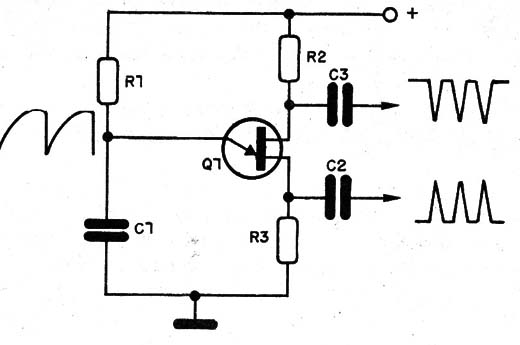
The operating range of this type of oscillator is very wide, ranging from a hertz fraction to the audible limit.
Thus, for very low frequencies when electrolytics are used, we will have the production of interval of pulses.
On a very slow relaxation oscillator (ultra-low frequency), we can use the multimeter as indicated in Figure 3.
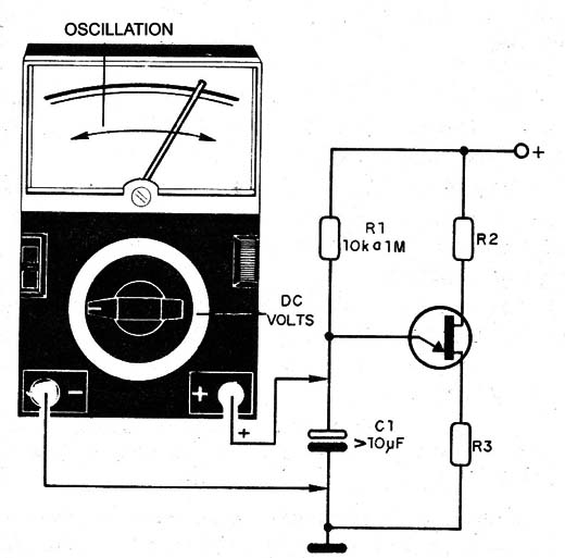
The pointer of the multimeter (which should have good sensitivity) will oscillate according to the charge and discharge of the capacitor.
In Figure 4 we have an oscillator with an integrated circuit 555 in astable configuration.
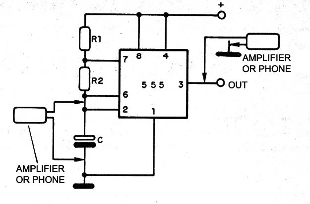
We can find this circuit generating signals that vary from less than 1 Hz on timers to above the audible range, reaching a few hundred kilohertz.
For the audible range we can connect the indicated points in Figure 4 to a high impedance earphone or amplifier.
For frequencies below the audible limit, like on timers, we can use a LED in series with a resistor to check the oscillation, as shown in Figure 5.
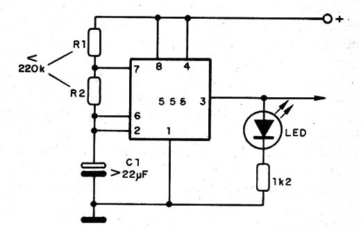
We can also use the same procedure of unijunction to verify the pointer oscillation of a multimeter connected in parallel to the capacitor.
The pointer should oscillate at a frequency that depends on the capacitor used.
For frequencies above the audible limit we can use a small AM radio outside a station like a sensor.
The astable circuit 555 generates a rectangular signal rich in harmonics which are irradiated and can be picked up by a nearby receiver.
Thus, the receiver will pick up the oscillator signal if it is working properly.
For other oscillators of audio range, up to several hundred kilohertz, which do not result in sound when working, we can use an AM receiver as a follower.
For very weak signals we can remove the circuit signal and apply it to the receiver antenna.
The same procedures also apply to the astable ??multivibrators, as shown in Figure 6.
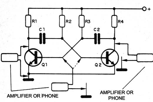
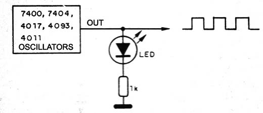
For TTL circuits, we have two possibilities.
If the signal is of high frequency, we can use a radio receiver and if of low frequency we can use either a transducer or a LED in series with a resistor, as shown in Figure 7.
Of course that more advanced features are much better, being able to determine the waveform and frequency of the signals generated, like the oscilloscope.
High Frequency Oscillators
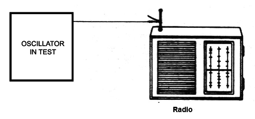
Oscillators of high frequencies, such as those used in small transmitters, super-regenerative receivers, instrumentation, emit signals which can be received nearby.
You just need to approach a receiver of a common radio out of the circuit station in test and try to capture its signal, as shown in Figure 8.
Another way to check the RF oscillator operation is using a multimeter as an RF meter.
Using a diode and a capacitor, as shown in Figure 9, we can transform a multimeter into an RF detector and check the presence of signals on circuits.
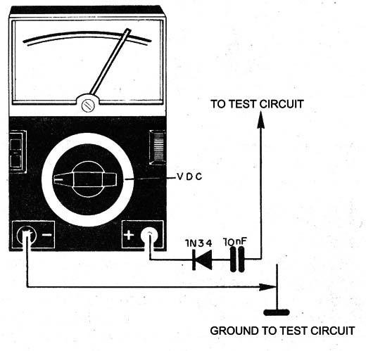
This circuit also verifies signal transmission of small transmitters.
Simply get the probe wire close to a transmitter or to a transmitting antenna to detect whether signals are being produced or not.
We can also use for this purpose a galvanometer of 200 µA or less.
In this case, the sensitivity will already be lower, but we can check if small transmitters are working.
To capture signals from one oscillator coil or from a coil of an amplification stage of a small transmitter, we can use a capture ring, as shown in Figure 10.
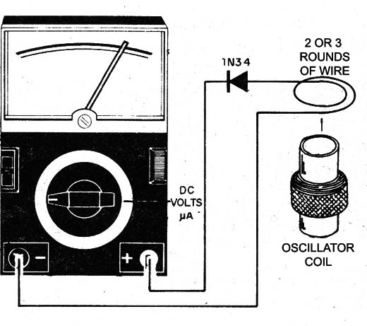
In all cases the multimeter will be in the lower range of DC voltages.
In both cases, we can use the lower range of alternating currents and the internal diode of the multimeter itself to detect the signals.
In these cases, we do not need the external diode, as we just need to get the probe close to the oscillator circuit and the instrument will indicate if it is oscillating or not.
For very low power circuits, we need to touch the probe somewhere on it, leaving the other probe free.
Finally, for transmitters or oscillators with power above 1 W we can use a hertz ring, as shown in Figure 11.
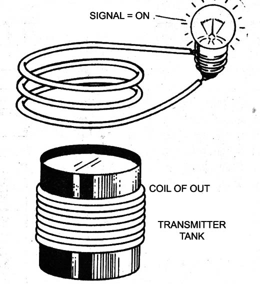
Getting a coil with a small pilot lamp (6 V - 50 mA) closer to the oscillator coil or to the output of a transmitter, the lamp should light up if its operation is normal.


