A signal follower is an amplifier with detection capabilities that can track both audio and RF signals (modulated in AM/FM amplitude or frequency) by troublesome circuits.
By searching on each stage for the signals that are presented, the technician and the user may reach the stages which do not work by isolating them. Then, just search for a component or components that specifically cause the operating problems.
In Figure 1 we have a simple circuit of a signal follower that uses an LM386 amplifier, and which is powered by common alkaline batteries.
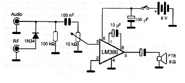
The circuit has two inputs, one for audio signals and the other for modulated RF signals, which make it possible to analyze the RF and FI steps of receivers and others.
The reader, however, can use any common amplifier as a signal follower.
An interesting way is to adapt a portable radio to this function. If the reader usually works by listening to music, his/her bench radio may have one more function operating as a signal follower.
To do this simply stop an audio signal track after the detector and before the volume potentiometer, by putting a little switch in its place.
In the potentiometer we connect the RF inputs by a diode and audio directly, as shown in Figure 2.
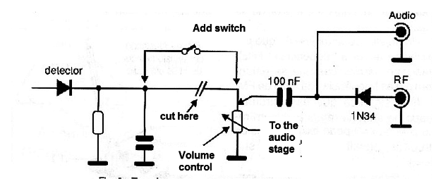
Having probes handy and ready, just plug-in them to the corresponding jacks and switch off the radio sound at the little switch so that the amplifier of the radio itself become a signal follower.
HOW TO USE
The basic idea of using the signal tracker is what should accompany the signal along the circuits.
Thus, we know that in the radio, the signal must be present from the output of the converter to the loudspeaker.
In the FI steps we have RF signals which have gradually increasing intensity, and after the detector we have audio signals in the intensity also gradually increase up to the loudspeaker.
If by following the signal we find a point where it disappears or its intensity decreases abnormally, it is because something wrong exists at this point. A signal distortion also indicates an abnormality.
Thus, taking as an example a traditional transistorized radio circuit, we have in the sequence of points from 3, the places where we should look for the signals with the follower. See Figure 3.
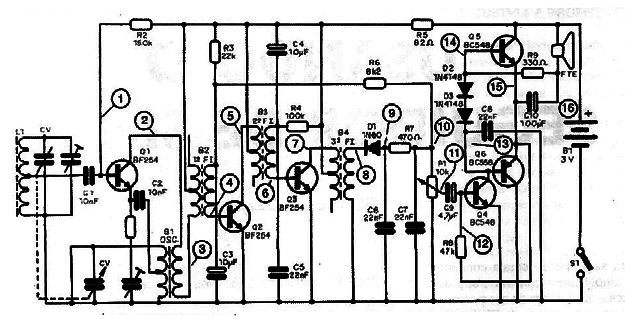
Starting from point 1 where we have an output of the oscillator/mixer, we go step by step, looking for this signal in the base and in the collectors of the transistors.
If we have coupling capacitors, we must check if the signal is before and also after the components.
An open capacitor does not give way to a signal, or makes it in a poor way, having a detection thereof with the follower.
If the signal decreases too much of intensity where it should be strong, it also indicates the mismatch of the stages. This occurs, for example, when analyzing the signals in the FI steps of a radio.
The adjustment made with an appropriate switch (wood or plastic) and having the signal follower as a reference, helps calibrate receivers that are far to their optimum operating point, as shown in Figure 4.
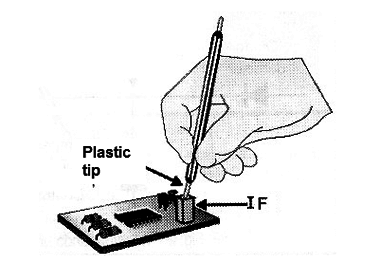
Looking for the signal in the first few steps and then step-by-step using the follower, can simplify for the technician who does not have other advanced features to calibrate a radio.
Note that the diagram shows the points at which you have RF signals and the points where you have audio signals.
In the specific case of a radio, such as the one exemplified, the signal used to verify the cause of a problem or a tuned station.
Whether working with a recorder, amplifier, cassette player or CD-player, the signal source can be a disk, tape or CD as well as a signal generator.
A feature widely used by technicians working with the signal follower is the signal injector.
An injector is nothing more than a low frequency oscillator (1 kHz), but with harmonics that extend up to the frequencies of the FM band.
This means that this circuit, connected to the input (antenna) of a radio (AM or FM) can excite all the circuits, allowing its analysis.
In Figure 5 we have a simple signaling circuit and a harmonic-rich rectangle signal, which can be very useful without the diagnosis of stereo and radio.
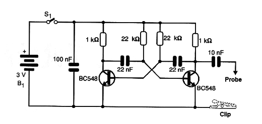
Even televisions, answering machines and cordless phones may have defects diagnosed with the help of this circuit.
The basic procedures for using the follower are:
A) Check if the circuit steps receive normal power using the multimeter. If the power supply is normal and the technician can not perceive any apparent problems for non-operation, proceed to the next item.
B) Switch on the instrument to be analyzed at normal operating condition (open volume, tuned with a program source or signal injector).
C) Verify if the signal is present at the input of the circuit by using the signal follower.
D) Gradually, search for the signal in the following stages, from input to output.
If the instrument is transistorized, the signals must be present at the base and then at the collector (or emitter), or at the transmitter and then at the collector (for common base configurations).
If you notice a change in the signal like a strong distortion, reduction of intensity or disappearance analyze the step in which this occurs.
E) Observe the steps in using the follower with audio or RF signals.
F) In RF steps a slight distortion of the signal may occur when analyzed by the very simple detection system (a diode).
G) Keep in mind that a signal when passing through an amplification step should come out of it with greater intensity than when entering, and that distortions should not be introduced.
CONCLUSION
In the repair forms posted on this site, the use of the signal follower is quite common, showing how technicians can use this equipment to diagnose problems. The great advantage of this instrument is its low cost, which makes it accessible even to readers who are starting now.
1999 (Revised 2017)


