The presented circuit, quite simple, is for testing capacitors of all types in the range of 10 nF to 100 uF, providing a sound indication. This is an interesting project to be set up for the bench and even for didactic purposes to understand how the circuit itself and the capacitors work. An idea would be to mount an experimental aluminum foil capacitor and prove its value with this test.
The basic idea is very simple: an oscillator whose feedback, and therefore the frequency of the sound to be produced, is determined by a capacitor. We put a good capacitor in the circuit and it works, causing the speaker to whistle or emit spaced clicks (depending on the value). If the capacitor is bad (open or shorted), there is no feedback and no sound is emitted.
Since the frequency of the sound depends on the value of the capacitor, with a little training and the use of known capacitor values, for comparison, we can even determine with certain precision how much is the value of a capacitor tested.
The circuit operates with voltages sources from 3 to 6 V (two or four common batteries) and is very simple to assemble.
How it works
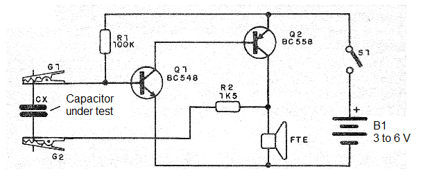
As we have explained, it is an oscillator whose frequency is determined by the capacitor under test and also by the resistor R1, which controls the polarization of the first transistor.
It is convenient for R1 to be in the range of 100 k to 470 k, if most of the tests are small capacitors (10 nF to 100 nF) and in the range of 10 k to 56 k if the tests are for larger capacitors (100 nF to 100 uF). You can even include a switch that switches the two capacitor values, depending on the tests.
The complementary transistor oscillator provides good power to the small speaker used. See that the sound will be all the louder the smaller the capacitor tested, if it is good.
Assembly
In figure 1 we have the complete diagram of the capacitor test.

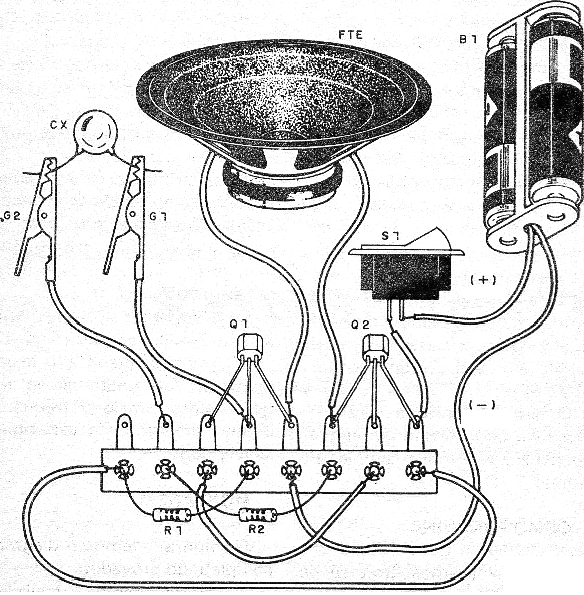
Figure 2 shows the assembly on a terminal strip, which is the ideal version for beginners. Of course, readers with more resources can mount them on a printed circuit board, or even in a matrix of contacts.

The circuit with the power supply and speaker can be housed in a plastic band. Two wires with alligator clips serve to connect the fitting to the capacitor under test.
We can also use a general switch to switch the appliance on or off. This component can be eliminated, in which case to disconnect the device, simply remove the batteries from the holder. The resistors are d 1/8 W and the transistors admit equivalent.
Testing and Use
After completing the assembly, place the batteries in the holder and connect a capacitor of any type between 47 nF and 100 nF between the test clips. There should be sound production on the loudspeaker. If this occurs, the unit is ready for use.
To use, just connect the capacitor under test between the claws. There must be sound emission. The sound will be all the louder the lower the value of the capacitor being tested. If you have known capacitors of values, you can do the sound comparison: sounds of tones very close, taking into account the tolerance of the components, indicate equal values.
For electrolytic capacitors from 1 uF, the sound produced will be in the form of intervaled pulses whose separation will be greater the higher the value of the capacitor being tested.
Q1 - BC548 or equivalent - NPN transistors of general use.
Q2 - BC558 or equivalent - general purpose PNP transistor
FTE - 4 or 8 ohm - small speaker 5 to 10 cm
B1 - 3 to 6 V - 2 or 4 small batteries
R1 - 100 k ohm x 1/8 W - resistor - brown, black, yellow
R2 - 1.5 k ohm x 1/8 W - resistor - brown, green, red
Miscellaneous:
Terminal strip, battery holder, alligator clips, mounting box, wires, solder, etc.


