Material:
B1 - 9 to 12 V source
R1 - 10 k ohm x 1/8 W - resistor
R2 - 470 k ohm x 1/8 W - resistor R3 - 100 ohms x 1/8 W - resistor
P1 - 1 M ohm - potentiometer
C1 - 10 nF for the oscilloscope or 1 uF for the multimeter
Procedure
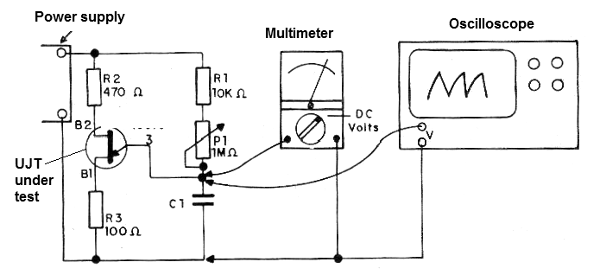
The test circuit is given in the figure below.

By adjusting P1 we should observe the oscillating instrument needle or the waveform generated on the oscilloscope screen.


