The test neon lamp may be bought ready or assembled easily at a low cost.
However, whatever is the origin of your test lamp, one thing is important: knowing how to use it on an electrical installation is something that every electrician needs.
If you want to build your test lamp instead of buying one that is ready, which is sold at supermarkets as shown in the photo, let's start from the beginning.
The neon lamp test
A neon lamp is a small glass bulb filled with neon inert gas and two metal electrodes, as shown in Figure 1.

When a voltage from 70 to 80 V is applied to this bulb, the gas is ionized, it becomes conductive and the lamp emits a weak orange light.
The neon lamp is a low current device requiring microamps to light, which means a great sensitivity in the detection of voltages above 80 V.
To prevent it to burn, it is directly connected to the power grid or to sources of higher voltages, we must turn it on in series a resistor of a very high value, as shown in Figure 2.

The result of this configuration is a sensitive device capable of detecting the presence of voltages above 80 V, be they continuous or alternated.
Even the leak voltage which escapes from devices having insulation problems can be detected by the neon lamp, due to its sensitivity.
If we want to build our test lamp we don’t need more than a neon lamp, a resistor and two wires with testing ends, as shown in Figure 3.
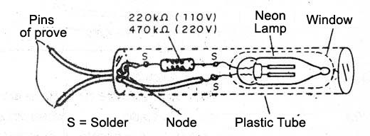
You just need to install it inside a small tube of cardboard or plastic with an opening that lets you see when it goes on.
Usages
The first utility of this device is to check the presence of tense in a plug, a key or even in a socket of a lamp.
You just need to touch the testing ends at the place and if the neon lamp lights up, we will acknowledge that there is a voltage of 110 V or 220 V, as shown in Figure 4.
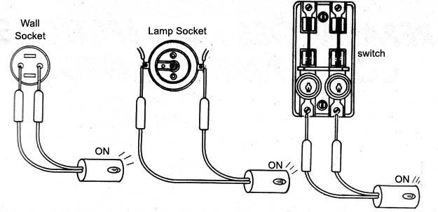
If the lamp does not light up, of course we will not have tension in the tested place.
Flip the switch, if you are testing lamps in their support.
A simple test of a circuit continuity with a lamp (or even its state), without climbing a ladder to remove it from the socket, is shown in Figure 5.
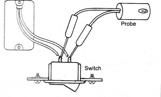
If the lamp lights up at one of the switch positions, then it is in good condition.
If it does not light up at any position, the lamp is burned.
If we open the key, the neon lamp lights up, it is a sign that there is continuity in the lamp circuit and, therefore, it is in good condition.
The problem may be at the key when it is closed and the lamp stays on, indicating that the circuit was not closed.
In Figure 6 we show a way to verify if the fuses are good without removing them from their holders at a general energy key.
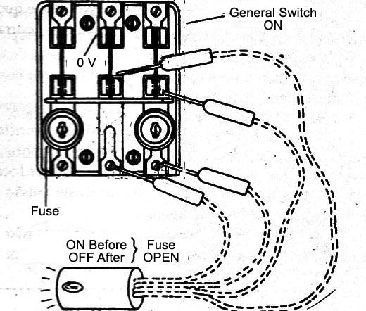
If the lamp lights up, the corresponding fuse is open.
In Figure 7 we have a way to check if a power cord of an appliance is with internal interruptions (very common in irons).

The neon light should turn on if the cord is in good condition.
An important test for the safety of an appliance is of the housing insulation.
If there is an internal accidental connection or a strong leak of any power cord and charge, it is dangerous that those who touch the appliance receive a strong shock.
Turning the device on and touching the neon lamp, as shown in Figure 8, we can test the insulation of the housing or chassis.
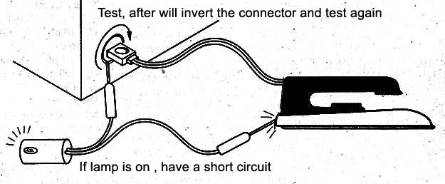
In the two power position plugs, the neon lamp should not light up.
In the case of irons if the lamp lights up weakly this indicates the presence of internal humidity with leaks into the housing, which can also cause small shocks.
The power supply system has conductors connected to the ground, as shown in Figure 9.
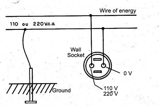
It is the living stage or pole which if touched causes shocks.
The neutral pole or earth, if touched causes no shock and can cases be used for grounding apparatus in some cases.
The identification of the neutral pole is made as shown in Figure 10.
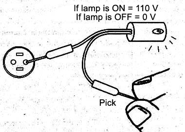
Holding between the fingers one of the poles we touch the others with the other tenting end.
Touching the live pole the lamp lights up, and touching the neutral pole the neon lamp remains off.
See that there is no danger in holding the lamp pole between our fingers, because the limiting resistor that is inside is usually high enough to limit the current to such a low value that does not cause shocks.
In practice using a ready-made bought lamp it is good to make sure that the internal resistor has over 150k, to take no shock when using the device in this way, as shown in Figure 11.
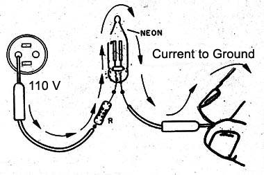
See, however, that to be safe the assembly must be perfect.
Safe testers are sold at very low prices at electric and electronic material stores, and even supermarkets, some also containing LED indicators for additional measures at low voltages.
The tester can also be used in power supplies for electronic devices such as analog televisions and old video monitors.
In Figure 12 we show how the tester can be used to check if a TV source is good and if the capacitor C1 is retaining its charge.
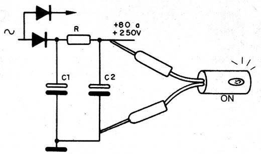
With the help of a 1N4004 or 1N4007 diode we can load capacitors with voltages up to 200 V if the network is 110 V and 400 V if the network is 220 V, to test its state, as shown in Figure 13.

We load the capacitor (observing the polarity, if it is electrolytic) and we turn on the neon lamp.
It should light up and stay this way for longer the greater it is the component capacitance in test.
For a capacitor of 8 µF, for example, it should be between 10 and 20 seconds on, if it is in good condition.
Voltmeter 110/127/220 V
In many places we have 110 V/127 V and 220 V voltages available in the same installation.
In them it is important to know if a plug where we will connect any type of device, the available voltage is either.
The neon lamp can be very useful in a simple voltmeter circuit shown in Figure 14.
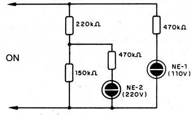
If one of the lamps light up it indicates that the voltage available at the place of testing is 110 V or 127 V.
If the two lamps are lit, the available voltage is 220 V.
The instrument is very compact and it can be carried in the pocket.
Instruments of this type can also be found in electrical and electronic equipment stores.
Remote monitor
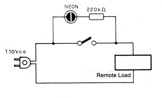
If the reader has in his/her house a remote trigger electrical device such as, for example, a water pump or a garden light, placing a monitor next to the trigger switch can be of great use.
With the marking of on-off on the switch, the reader does not need to go to the device to know how it is.
You just need to look at the switch observing the indication of the neon lamp, as shown in Figure 15.
Conclusion
One of the great advantages of the neon lamp is its very low consumption, almost nil.
It is fractions of thousandths of a watt that do not affect energy consumption, even if it is used in large quantities.
Moreover, we have its great utility and low cost.
On our site we have dozens of articles which uses neon lamps as a main component.


