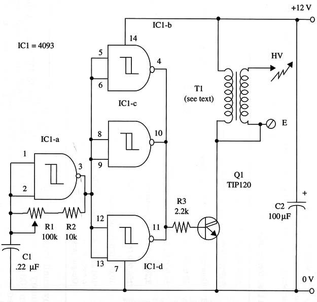
The circuit is formed by a 4093 arranged as a low-frequency oscillator (IC1-a) and a buffer (IC1-b, c, and d) driving a Darlington power transistor (or a power FET if you prefer).
The transistors load is a common car ignition coil that produces the desired high voltage in its secondary. R1 can be adjusted for better performance of the circuit, and the voltage depends on the coil employed.
An ac-to-dc converter can be used to power the circuit in the laboratory, and you can also use a car battery or eight D NiCad or alkaline cells. Current drain depends on R1 adjustment.
Sparks ranging from 1/10 to 1/2 inch can be obtained between HV and E terminals.
A schematic diagram of the Experimental HV Generator is given in Fig. 1.

The transistor must be mounted on a heatsink. T1 is an ignition coil
like the ones used in cars. Any type is suitable for this project. The po-
sitions of the polarized components must be observed.
R1 adjusts the oscillator frequency for better performance.
As an experiment, position a fluorescent lamp or neon lamp near the
high voltage terminal. It will glow, and no contact is needed. A dark ambient produces better results.
IC1- 4093 CMOS integrated circuit
T1 - Any car ignition coil (see text)
Q1 - TIP120 N PN Darlington power transistor
R1 - 100,000 ohm, potentiometer
R2 - 10,000 ohm, 1/4 W, 5% resistor
R3 - 2,200 ohm, 1/4 W, 5% resistor
C1 - 0.22 µF ceramic or metal film capacitor
C2 - 100 µF, 16 WVDC electrolytic capacitor


