This circuit activates an emergency lighting system when the mains power is cut off. Linked to a smart system it can only be triggered at night when we do not have natural light. However, in places where natural light does not arrive, it does not need any additional elements.
The circuit has as an important additional feature a charger that keeps the battery or rechargeable batteries ready to be used. The autonomy will depend on two factors: the capacity of the battery or batteries used and the current required by the lighting system that will be triggered. An ordinary Nicad battery powered by a cell phone, for example, can power a small flashlight bulb for a few hours.
In modern versions you can use LEDs or even an inverter to power fluiorescent lamps.
AA rechargeable batteries can also power small light bulbs for the same time. Already, a motorcycle battery can power larger bulbs for longer.
Operation
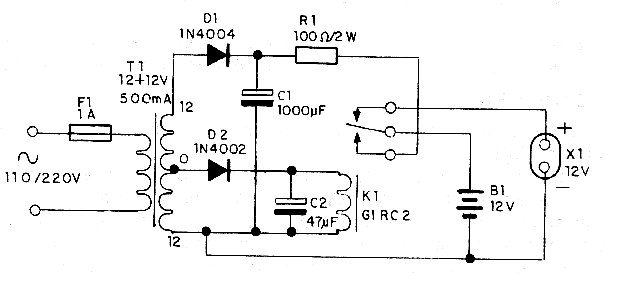
The complete inverter diagram is shown in figure 1.

At the input of the circuit we have a small transformer that reduces the voltage of the power grid to two values. The larger voltage value is rectified, then passed through a small filter capacitor which is C1. Next, this voltage of the order of 35 V goes through a current limiting resistor going to the battery on charge.
The limiting resistor value determines the charge current of the battery. For larger batteries, we limit it to 200 mA, but for small AA or cellular batteries, the resistor must have its value doubled. Check the battery for charging conditions to size this resistor. In our case we use 100 ohm, but values ??in the range of 220 ohms to 470 ohm can be used for lower power consumption.
The other sector of the transformer has a rectifying and filtering system whose purpose is to keep the coil of a relay energized. This relay is intended to connect the battery to the charging system until the power is cut off. When this occurs the relay switches and connects the battery to the lighting system.
The circuit can be easily coupled to a smart system in series with the external lighting system, so that it will only be triggered if the location is dark. Note that the supply voltage can be either 110 V or 220 V, depending only on the transformer used.
Assembly
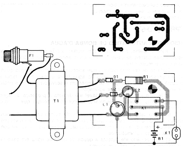
The arrangement of the components on a printed circuit board is shown in figure 2.

The transformer used has a primary winding according to the mains voltage and a secondary one of 9 + 9 V or 12 + 12 V with at least 300 mA of current. The diodes can be of type 1N4004, as indicated in the diagram. The capacitors must have working voltages as indicated in the material list. The resistor R1 must have dissipation of at least 2 W, and be of the wire type.
The relay accepts equivalents, depending on the transformer secondary voltage. The battery can be harnessed from a mobile phone in which case the lamp will be 4.5 V or 6 V or even 4 AA batteries for 6 V lamp and possibly as shown in the diagram a 12 V battery with lamps of the same voltage .
Testing and Use
To test it, simply connect the system to the power grid. The relay should close its contacts, indicating that its coil is being supplied. Then simply install the device, conveniently positioning the battery and the bulbs. We note that if unsealed lead-acid battery is used it should be kept in a ventilated place.
D1 – 1N4004
D2 – 1N4003
R1 – 100 ohm x 2 W
C1 – 1 000 uF x 50 V
C2 – 470 uF x 25 V
T1 – 127/220 V x 12 + 12 V x 500 mA
F1 – 1 A
K1 – 12 V – contact 10 A
X1 – 12 V lamp
Printed circuit bord, power cord, wires, etc..


