We present a 6, 9 or 12 V fixed power supply design with 500 mA or 1 A current that can be used to power small electronics such as AM / FM radios, toys, small keyboards, etc. The circuit is regulated which provides excellent performance for many powered devices, unlike those disposed of conventional batteries that mostly do not have regulation.
How it works
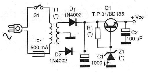
In this circuit, the transformer lowers the voltage of the power grid, which is rectified by D1 and D2, and then filtered by the electrolytic capacitor. The regulation is done by a step containing a zener diode and a power transistor. In function of these components and the resistor R1 we have the output voltage and the maximum current, according to the following table:
| Output voltage | Current (ma) | Transistor o | Zener | Resistor R1 | Transformer |
| 6 V | 500 mA | BD135/137/139 | 6 V x 400 mW | 270 ohm x 1 W | 7,5 + 7,5 V x 500 mA |
| 6 V | 1 A | TIP31A/B/C | 6 V x 400 mW | 220 ohm x 1 W | 7,5 + 7,5 V 1 A |
| 6 V | 500 mA | BD135/136/137 | 6 V x 400 mW | 330 ohm x 1 W | 9 + 9 V x 500 mA |
| 6 V | 1 A | TIP31/A/B/C | 6 V x 400 mW | 270 ohm x 1 W | 9 + 9 V x 1 A |
| 6 V | 500 mA | BD135/137/139 | 6 V x 400 mW | 470ohm x 1W | 12 + 12 V x 500 mA |
| 6 V | 1 A | TIP31/A/B/C | 6 V x 400 mW | 390 ohm x 1 W | 12 + 12 V x 1 A |
| 9 V | 500 mA | BD135/136/137 | 9V1 x 400 mW | 220 ohm x 1 W | 9 + 9 V x 500 mA |
| 9 V | 1 A | TIP31/A/B/C | 9V1 x 400 mW | 150 ohm x 1W | 9 + 9 V x 1 A |
| 9 V | 500 mA | BD135/136/137 | 9V1 x 400 mW | 220 ohm x 1 W | 12 + 12 V x 500 mA |
| 9 V | 1 A | TIP31/A/B/C | 9V1 x 400 mW | 270 ohm x 1 W | 12 + 12 V x 1 A |
| 12 V | 500 mA | BD135/136/137 | 12 V x 400 mW | 220 ohm x 1 W | 12 + 12 V x 500 mA |
| 12 V | 1 A | TIP31/A/B/C | 12 V x 400 mW | 180 ohm x 1W | 12 + 12 V x 1 A |
In all cases, if a transformer with secondary current less than the expected maximum is used, this will be the current obtained from the source.
Assembly
In figure 1 we have the complete diagram of this source.

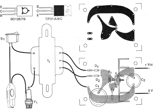
There are several techniques that can be used for assembly. If printed circuit board is used, the pattern of Figure 2 may serve as a basis.

Capacitor C1 must have a working voltage of at least 50% than the secondary voltage of the transformer used. The transistor must be provided with a good heat radiator. Note that the terminal arrangement of the BD series transistors is different from the TIP series.
Q1 - BD135 or TIP31 - according to current - see table
D1, D2 - 1N4002 - Silicon rectifying diodes
C1 - 1 000 uF - electrolytic capacitor - see text
C2 - 100 uF - electrolytic capacitor - voltage slightly higher than that of the source output.
R1 - Resistor according to version - see table
Z1 - See table
T1 - Transformer - see table
S1 – On/Off switch
F1 - 500 mA - fuse
Miscellaneous:
Terminal strip or printed circuit board, power cable, transistor heat radiator, fuse holder, mounting box, wires, solder, etc.


