Sensitive directional microphones are very interesting assemblies and are not very difficult to perform with low cost components. The amplifier we describe feeds a headset, is powered by batteries and has excellent sensitivity thanks to the use of an electret microphone.
A special control makes it possible to increase its gain in situations where the sounds are weaker, thus facilitating the hearing. Suggested practical applications are as follows:
Spying
Recording of nature sounds
Sports Apps
Detection of remote sounds in robots with the use of a transmitter
The main characteristics of the circuit we describe are:
Characteristics:
Supply voltage: 6 or 9 V (4 or 6 small batteries)
Controlled Gain (50x or 200x)
Output power (200 to 400 mW - depending on the suply, and output impedance)
Output impedance: 4 to 16 ohms
How it works
There are two basic techniques for picking sounds directionally. One is the use of a pipe to "channel" the sounds and is often used in soccer stadiums to capture the sounds of kicks and the players' own talk. The second consists of positioning the microphone in the focus of a parabolic reflector and is used mainly in the recording of bird sounds and other sounds of nature. The two techniques are illustrated in Figure 1.
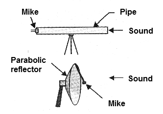
Our design uses the second technique with a reflector which can be any metal or hard plastic object of at least 40 cm in diameter and that has a curvature which approaches the parabolic. We can use, for example, a half sphere of a globe of light effects with satisfactory results. The exact point at which the microphone should be positioned will be obtained experimentally.
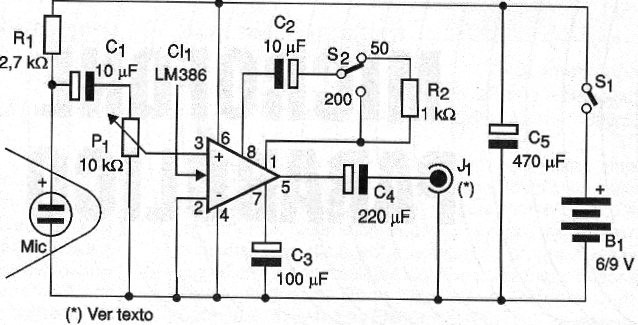
The signal picked up by the electret microphone is taken to the circuit through a shielded cable, to avoid buzzing. Interleaved between the microphone and the amplifier input we have the potentiometer P1 which works as a volume control. The amplifier used is an LM386 which, in addition to being easy to find and inexpensive, requires few additional external ones to get good gain, and low impedance output. The gain of this amplifier is determined by the resistor R2 in the negative feedback circuit. Thus, with the switch in position, where this resistor is in the circuit, the gain of the amplifier will be 50 times.
By changing the position of the switch so that only the capacitor is in the circuit, the gain will be 200 times. The capacitors C3 and C5 decouple the amplifier and the source respectively and the capacitor C4 makes the coupling to the load which may be a low impedance earpiece. Padded types are the best results in this type of application by blocking any other type of sound other than what comes from the circuit.
Assembly
In Figure 2, we give the complete circuit of the parabolic microphone.
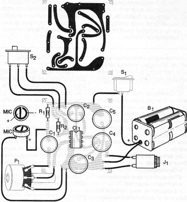
The electronic part may be built on a small printed circuit board with the arrangement of components shown in Figure 3.
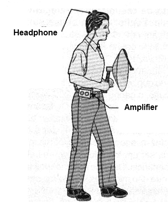
The entire assembly fits in a small plastic box which can be built either side of the reflector or loaded onto a shoulder strap, as shown in Figure 4.
In any case, it is important to use shielded cable to connect the microphone, because the amplifier is sensitive and can pick up hum. In the assembly, observe the polarity of the electrolytic capacitors and the position of the integrated circuit. It is also important to note the polarity of the electret microphone, since if it is reversed the appliance will not work.
The resistor R1 determines the polarization and gain of the field effect transistor that exists inside the electret microphones. Eventually, this resistor can be changed to find the point of greatest sensitivity. Values ??between 2.7 k ohms and 10 k ohms can be experienced. For the output of the handset we have two possibilities shown in Figure 5.
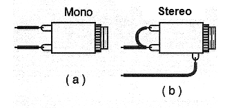
In the first case the jack is simple for monophonic headset. In the second case, if we use a stereo jack for a stereo headset, the connection must be made with the channels in series.
Test and Use
To test the device simply connect S1, open P1 and check the environment sounds pickup with the S2 switch in both positions in order to compare the gain.
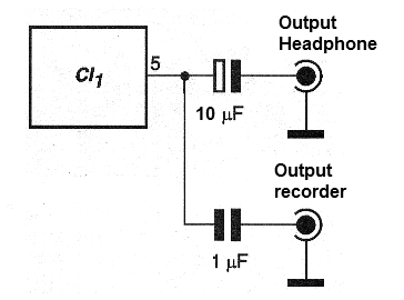
If there is a rumbling on the handset, check the shield of the microphone cable and if its mesh is firmly attached to the earth ground of the circuit. It is only necessary to use the circuit. To make recordings, a parallel output can be used, which will be connected to the MIC input of the recorder, as shown in Figure 6.
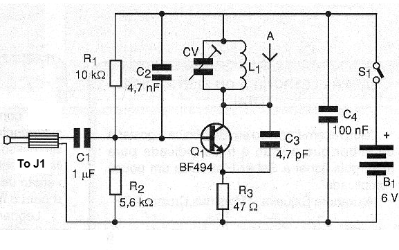
This same output can be connected to a small FM transmitter, such as that shown in Figure 7, for the reception of signals at a distance.
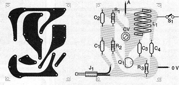
A printed circuit board for the transmitter is shown in Figure 8.
In this circuit, the coil consists of 4 turns of enameled wire 22 to 26 AWG or even common hard wire (of the type used in telephones) in a pencil as a reference.
The capacitors with values expressed in nF and pF must be ceramic. The antenna consists of a 20 to 40 cm piece of rigid wire or a common radio telescopic antenna. The range can reach 50 meters in an open place and free from interference. The signal is received on any stereo with FM, preferably with analog tuning.
a) Microphone
Semiconductors:
CI-1 - LM386 - integrated circuit, amplifier
Resistors: (1/8 W, 5%)
R1 - 2.7 k ohms - red, violet, red
R2 - 1k ohms - brown, black, red
P1 - 10 k ohms - common potentiometer lin or log
Capacitors:
C1, C2-10 uF x 12 V - electrolytic
C3 - 100 uF x 12 V - electrolytic
C4 - 220 uF x 12 V - electrolytic
C5 - 470 uF x 12 V - electrolytic
Several:
MIC - two-terminal electret microphone
S1 - Single switch
S2 - 1-pole wrench x 2 positions
J1 - jack according to the phone - see text
B1 - 6 or 9 V - 4 or 6 small batteries


