The electronic thermometer we describe is very simple, but this does not in any way affect its sensitivity and readiness and is therefore ideal for school experiments where measuring temperature or variations is necessary.
The sensor used is a diode of low thermal capacity thus allowing readings in the range of -50 °C to approximately 125 °C.
The calibration of the scale will depend on the type of use the apparatus will have, and it is observed that normally the entire scale can not cover the suggested operating range for the diode. An appropriate range should be chosen.
The circuit is powered by two batteries which, given the very low current consumption, will have very long life.
The thermometer can be used to:
- Indicate the room temperature;
- Indicate the temperature of solutions and greenhouses;
- Measure rapid temperature variations of components;
- Detect "leaks" of heat.
How it works
As noted in the introduction, the sensor element that serves as the basis for this design is a common diode (BA315, 1N4148, or any other silicon).
These diodes when polarized in the reverse direction, as shown in figure 1, have a very high resistance to current flow.
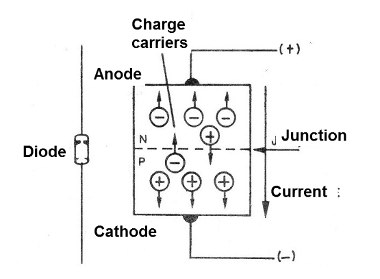
The small circulating current is due to charge carriers, which are released at the junction by the thermal stirring movement of the atoms of semiconductor material.
With this, it is found that if the increase in thermal agitation occurs, more charge carriers can be released and therefore more current can flow through the diode.
In fact, it is found that the current flowing through the diode can have large variations in intensity as a function of the temperature of the component.
We can use diodes as efficient temperature sensors, simply by establishing a relationship between the conducting current and the temperature.
And of course we can not put the diode in contact with temperatures that put its integrity at risk, so that this type of sensor has its range of use limited to the values given in the introduction.
Using a current amplifier circuit with two transistors, we obtain such sensitivity of the circuit, that small variations of temperature can be detected promptly.
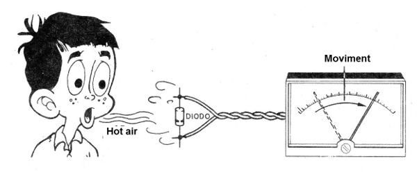
It will suffice to "bake" the diode so that the instrument needle moves quickly (figure 2).
Assembly
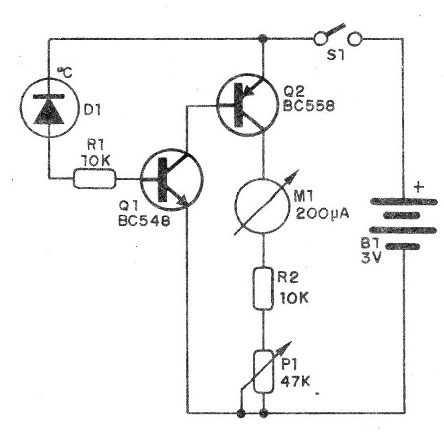
In figure 3 we have the complete circuit of the electronic thermometer.
In figure 4 we have its practical realization, based on a small terminal strip.
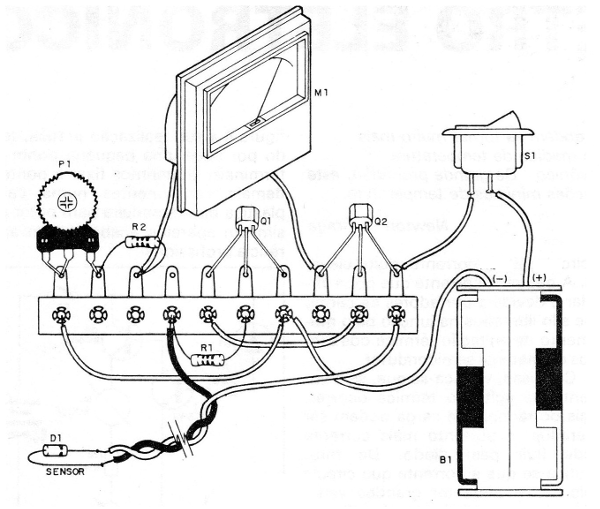
We suggest fixing the bridge and other components in a plastic or wooden box to obtain a finished, professional-looking device.
The following are the main precautions that must be taken when assembling and obtaining the components:
a) The NPN transistor (Q1) may be BC548 or its equivalents such as BC237, BC238, BC547 and BCB49. For Q2 we use a BC558, or equivalents like BC307, BC309 or BC557. The position of these components should be observed carefully;
b) The M1 instrument is a 200 uA VU-meter. An appropriate scale may be made depending on the use of the appliance. Observe the polarity of the connections. If there is no marking, simply reverse the threads if the needle is to the left;
c) The Sensor may be any general purpose silicon diode. In the prototype we use the 1N4148. Observe its polarity. The connecting wire must have a maximum of 1 meter;
d) P1 is a trimpot of 47 k and the resistors are all 1 / 8W or ¼ W, depending on their availability;
e) S1 is a simple switch. The holder of the two batteries must have the polarity observed.
Finishing the assembly, check everything before doing the functional test.
Test and Use
Insert the batteries into the cradle and turn S1 on.
Put D1 on the soldering iron about 3 or 4cm in order to receive its heat, as shown in figure 5.
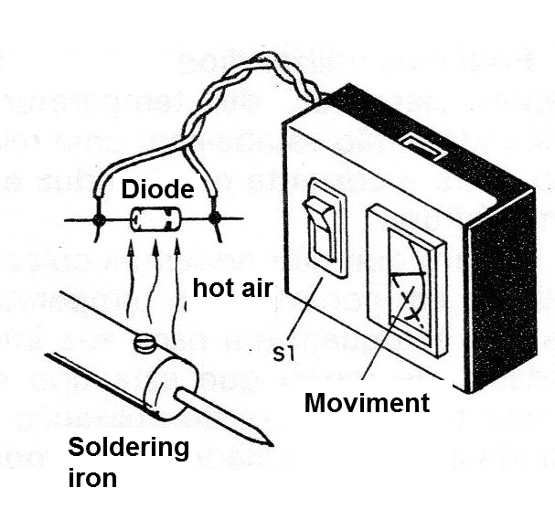
The instrument needle should go to the right as the diode temperature rises. Set P1 so that the pointer does not exceed the end of the scale (do not let the diode touch the iron!).
After that, just use the thermometer on the diode to see how it responds to temperature variations.
In order to use the device as the temperature of liquids, the diode must be insulated. One suggestion is to place it on the tip of a ballpoint pen tube, as shown in figure 6, and make an epoxy cover to prevent your contacts from getting wet.
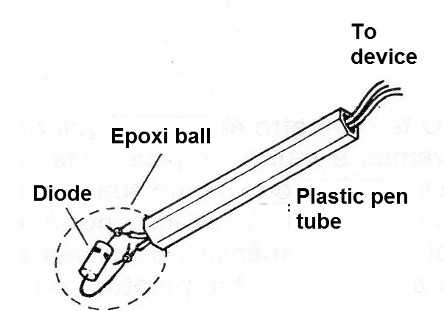
Establishing a scale for the instrument can be done by taking a standard thermometer as a basis.
To detect component heating in a circuit, an important application of it, simply press the diode on the suspect component.
Q1 - BC548 or equivalent - NPN transistor
Q2 - BC558 or equivalent - PNP transistor
D1 -1N4148 - diode (see text)
M1 - 200 uA VU-meter
S1 – On-Off switch
R1, R2 -10 k x1 / 8 W - resistors (brown, black, orange)
P1 - 47 k - trimpot
B1 - 3 V - two small batteries
Miscellaneous: terminal strip, wires, mounting box, tip to house the sensor etc.


