
ART2964S ART147
In this article, we describe two digital switches that operate in different ways, although both are based on CMOS digital integrated circuits. The first is a sequential digital switch that will activate a single relay only if the four programmed keys are pressed in a specific sequence.
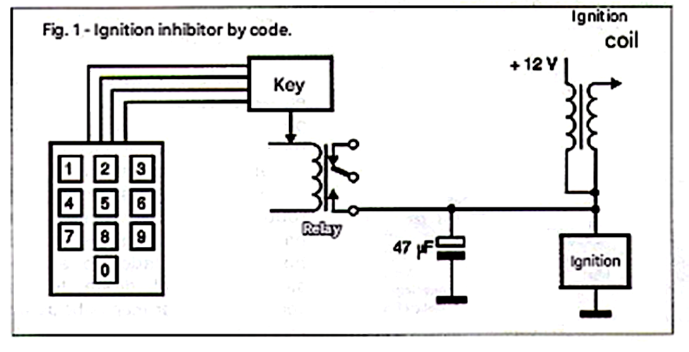
This configuration can be used in security systems or as a code key in alarms. In the simplest case, we have a car security system where the ignition device will only be released if a specific code is entered on a keypad, as shown in Figure 1.
Other applications include access to restricted areas in a company where the lock will only be released if a four-digit code is entered. The second circuit consists of a priority switch system with 3 relays, activated by push-button switches.
This circuit operates in such a way that only one relay can be activated at a time. Pressing one of the switches triggers the corresponding relay, and at the same time inhibits the activation of either of the other two relays in the same circuit.
Among industrial applications, we have the impossibility of activating a particular machine if another is still in operation. Another application, for those who like to assemble their own sound systems, is the selection of input channels of an amplifier by simple touch, in a kind of touch-selectable switch.
We can also use the same circuit in tests and classes where each competitor has a switch in their hand and, at a signal, only the one who pressed it first will cause an indicator lamp to light up, or some type of device to be activated. This circuit, in its basic version, uses three relays, but it can be expanded because there are gates available on integrated circuits that can be used for this purpose.
CIRCUIT 1
SEQUENTIAL SWITCH
This circuit will activate a relay only when all four switches (S1 to S4) are pressed sequentially. If the circuit is used in security systems activated from a keypad, the keys not used in the code can be connected to an alarm.
THE CIRCUIT
The basis of this project is the 4013 integrated circuit, which consists of two D-type flip-flops. Two of these integrated circuits are used, resulting in a set of 4 flip-flops connected in series.
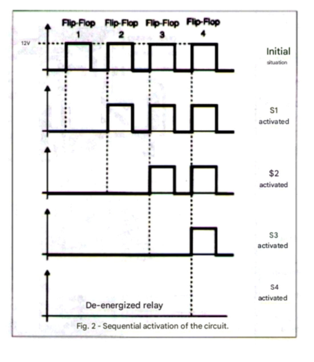
All "Clear" inputs are joined and connected to ground through a 1 MΩ resistor and to the positive power supply through a 220 nF capacitor. The purpose of this connection is to ensure that, when the circuit is connected to the power supply, all flip-flops are reset and start from the same initial state, with their outputs at level 1 (HI), see Figure 2
Depending on the application, the resistor can be reduced to 10 kΩ and the capacitor to 47 nF to obtain a faster reset. With the initial output level high on all flip-flops, the relay engages, inhibiting, for example, the starting of a car or keeping a load switched off.
To deactivate the relay and consequently disinhibit the ignition system of a car, or to disconnect a load connected to the normally closed (NC) contacts of the relay, we need to bring the output of the fourth flip-flop in the sequence (pin 1 of IC2) to a low level (LO). To do this, we must sequentially activate switches S1 to S4, because with each press, we will enable the next flip-flop in order to obtain the data transfer (switch press) that will bring its output to level 0 (low).
Note that pressing a key is useless if the previous one has not been pressed first, as the flip-flop will not be able to change the state of its output. This makes it mandatory to observe the programmed sequence. We also observed that it is possible to reverse the operation by activating the relay at the end of the sequence, simply by activating the relay with a PNP transistor. In this case, the transistor's emitter goes to the positive terminal and the collector to the relay.
ASSEMBLY
The complete diagram of the first circuit is given in Figure 3.
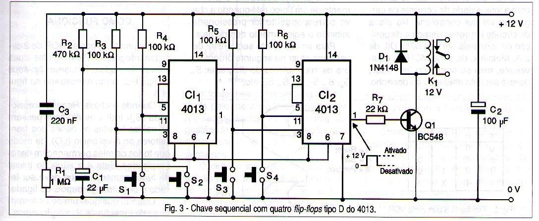
Figure 4 provides a suggested printed circuit board layout for this assembly.
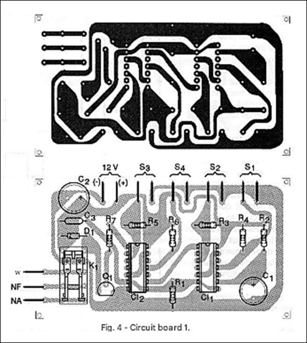
We suggest that before assembling the circuit board, the reader has all the components on hand, as variations in dimensions may occur, especially in the case of capacitors and the relay itself, which accepts equivalents. During assembly, it is advisable to use sockets for the integrated circuits and, depending on the type, also for the relay. The diode in parallel with the relay serves as protection for the transistor, preventing transients generated during the switching of a highly inductive load, such as its coil, from causing problems. Any general-purpose silicon diode can be used for this purpose.
The drive switches (S1 to S4) can be normally open (NO) push-button switches or, alternatively, they can be keypad switches where the keys not part of the programming would be connected between the positive power supply and the Reset pins of the integrated circuits (pins 8 and 6) to reset the circuit in case of an error. The electrolytic capacitors C1 and C2 must have the minimum working voltage indicated in the parts list.
The relay used must be compatible with the current intensity of the load to be controlled. On the printed circuit board, we have provided the terminal layout for 2A DIL relays, MCH series or equivalent, but if another type is used, the design must be modified. In a vehicle immobilizer system, the relay contacts can be used to connect a 47 µF x 100 V capacitor between the coil, and ground (contact points), which will prevent the ignition system from operating.
MATERIAL LIST - Circuit 1
Semiconductors:
IC1, IC2 - 4013 - CMOS integrated circuits (D-type flip-flops)
Q1 - BC548 or equivalent - general-purpose NPN transistor
D1 - 1N4148 or equivalent - general-purpose silicon diode
Resistors: (1/8 W, 5%)
R1 - 1 M ohms
R2 - 470 k ohms
R3, R4, R5, R6 - 100 k ohms
R7 - 22 k ohms
Capacitors:
C1 - 22 µF/12 V - electrolytic
C2 - 100 µF/12 V - electrolytic
C3 - 220 nF - ceramic or polyester
Miscellaneous:
K1 - 12 V x 50 mA relay - see text
S1, S2, S3, S4 - Normally Open (NO) Pushbuttons - see text
Printed circuit board, sockets for integrated circuits, mounting box, power supply, wires, solder, etc.
CIRCUIT 2 - SEQUENTIAL PRIORITY SWITCH
This circuit allows a single relay to be activated when its corresponding switch is pressed, inhibiting the activation of the others. For sequential activation, the switches in the diagram must be operated in the following order: S1, S4, S2, S4, S3, S4, S1, etc. This circuit can be used to control industrial mechanisms that only allow individual operation. Another application is in theater lighting systems where the circuit can control spotlights using TRIACs. The circuit is powered by a 12V supply, which can come from a source with at least 500mA. This source must be stabilized for safer operation.
HOW IT WORKS
Six NOR gates from two 4001 integrated circuits are used, connected in pairs to form RS-type flip-flops, as shown in Figure 5.
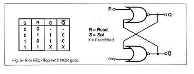
When the Reset switch (S4) is pressed, all flip-flops switch the outputs connected to the transistor bases to a low level (LO), so all relays remain de-energized. This is the initial operating state to which the circuit should be brought immediately after being switched on. When any of the push-button switches S1 to S3 is pressed, the corresponding flip-flop will change state, bringing its output to a high level, and thus the corresponding relay will have its coil energized.
A diode matrix acts to inhibit the activation of the other relays simultaneously. This is achieved because when a relay is activated, the diode matrix causes the base voltage of the other transistors to drop practically to zero, thus diverting any high level applied to them to ground.
ASSEMBLY
Figure 6 shows the complete diagram of this device.
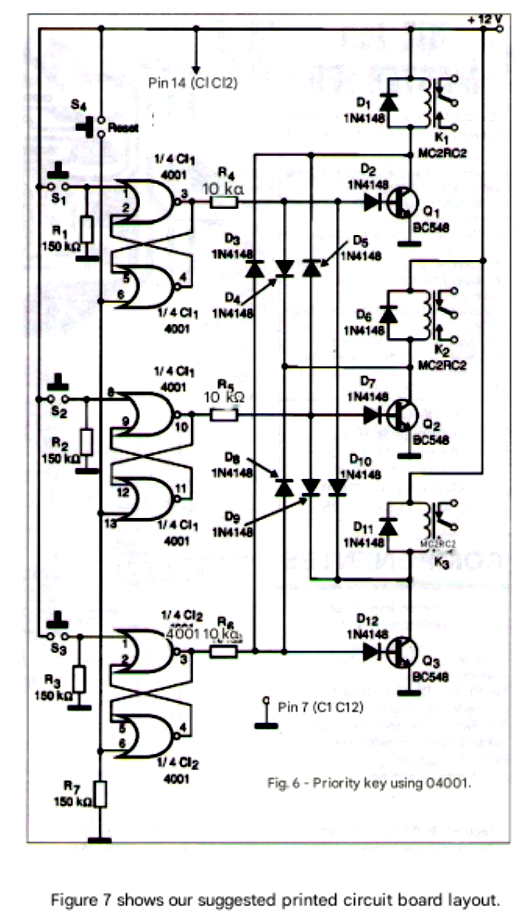
Figure 7 shows our suggested printed circuit board layout.
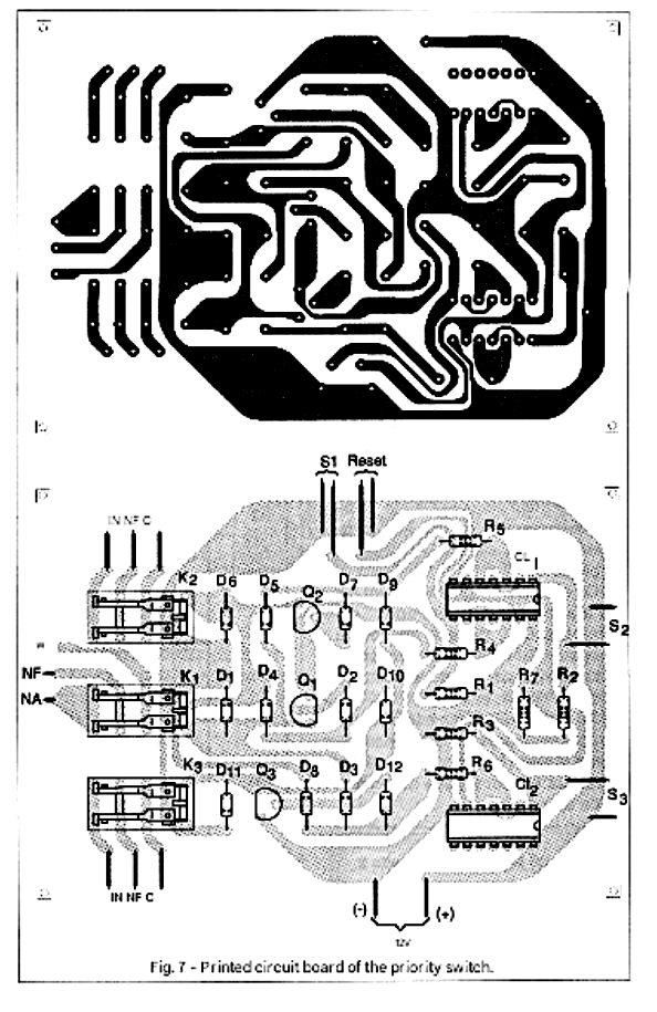
This board was designed for Metaltex MCH series relays, which fit a 14-pin DIL socket. If another type of relay is used, the board design must be modified. Integrated circuits should preferably be installed in DIL sockets, according to the pinout. Diodes can be of any general-purpose type such as 1N4148, 1N914, etc. The operating switches are normally open (NO) push-button switches and can even be mounted on a keyboard depending on the application. The power supply must provide a current of at least 500 mA with 12 V regulated. Figure 8 shows a suggested power supply that works for both projects presented.
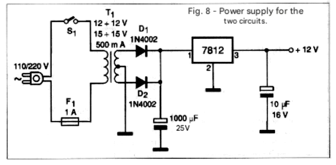
The 7812 integrated voltage regulator circuit for the power supply should be fitted with a small heat sink. The transformer has a 12 or 15 V secondary winding, with a current of 500 mA or more. The primary winding should match the local mains voltage.
Note: It is not advisable to install the operating switches too far from the device, as this could introduce noise, causing erratic operation of the switches. In this case, shielded wire should be used.
MATERIAL LIST - Circuit 2
Semiconductors:
IC1, IC2 - 4001 - CMOS integrated circuits
D1 to D12 - 1N4148 or equivalent - general-purpose silicon diodes - see text
Q1, Q2, Q3 - BC548 or equivalent - general-purpose NPN transistors
Resistors:
R1, R2, R3, R7 - 150 k ohms
R4, R5, R6 - 10 k ohms
Miscellaneous:
K1, K2, K3 - 12 V x 50 mA relays - Metaltex or equivalent - see text
Printed circuit board, power supply material, sockets for integrated circuits, wires, enclosure, etc.


