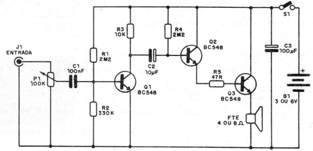
The described amplifier uses 3 general purpose transistors, which are connected in two configurations we studied: common emitter and common collector.
It will provide power of up to 1/2 watt to a 4 or 8 ohm speaker, and can be used as a base for a radio, intercom, or in the pickup, microphone, and other transducer type.
Circuit power can be supplied with 2 or 4 small batteries, or 3 to 6 V supply.
The main feature of this very simple amplifier is the use of common components: only transistors, resistors and capacitors are used in the steps, and as different elements we have only the volume control (P1) and the speaker.
HOW IT WORKS
The first amplification stage has Q1 turned on in the common emitter configuration.
The signal is applied, via volume control (P1), to the base of the transistor. The resistors R1 and R2 are intended to polarize the base of the transistor.
They establish the small base current that will vary with the presence of the audio input signal.
The amplified signal is withdrawn from the collector of the transistor and passes to the next step through the capacitor C2.
The next step is an improvement of the known collector or emitter follower stage.
By connecting two transistors so that their collectors are united and the emitter of the first goes to the base of the second, we form a Darlington transistor, that is, a double transistor whose gain is the product of the gains of the two transistors.
If the gain of each transistor is 100 times, the total gain obtained will be 10 000 times.
The signal will then be applied to the base of Q2 and drawn from the emitter of Q3 directly to the speaker.
See then that the ratio of values between R4 and the speaker accurately translates the gain of the circuit and also indicates the input and output impedances of the step.
We then have a high impedance input, which marries the previous step, and a low impedance output, which marries the used speaker.
We use NPN transistors. We could use PNP transistors by reversing the power and polarity of C2 and C3, which are the other polarized components of the circuit.
ASSEMBLY
The complete diagram of this simple amplifier is shown in figure 1.

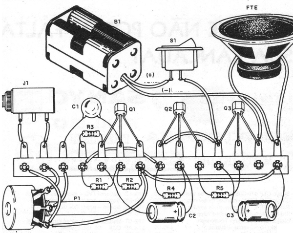
In figure 2 we have an assembly for beginners, realized in a terminal strip, which can be fixed in base of insulating material or box.

For the transistors practically any kind of general use can be experienced, for example: BC237, BC238, 80239, BC547, BC549, BC107, BC108, BC109 etc.
The resistors are not critical and in the case of R2 and R3 their values ??can be altered in order to find a combination that provides greater amplification without distortion.
The same occurs with R4 whose value, depending on the gain of Q2 and Q3, can be between 1M5 and 4M7.
If a power transistor such as a TIP31 mounted on a heat radiator is used instead of Q3 and the power supplied at 9 or 12 V, the power of the circuit will rise considerably.
Capacitors C2 and C3 must have a working voltage equal to or greater than the source. C1 may be of any type.
If a source is used, it should have good filtration to avoid tinnitus problems.
TEST AND USE
Simply connect S1 and connect a crystal microphone or other signal source to the J1 input, such as the audio output of a battery radio.
In the absence of these elements, it is enough to touch with the fingers in the alive terminal of the entrance (that goes to P1).
There should be sound or snoring when we open P1.
The operation is only used, remembering that you should always connect weak sources of signals to your input and that dynamic microphones, or other low sensitivity, can not excite this circuit without a preamplifier.
Q1, Q2; Q3 - BC548 or equivalent general purpose NPN transistors
S1 - single switch
B1 - 3 or 6 V - 2 or 4 small batteries or power supply with at least 500 mA
J1 - P2 or RCA type jack
FTE - 10 speaker with 4 or 8 ohms
P1 - 100 k - potentiometer (lin or Iog)
C1 - 100 nF - ceramic capacitor, polyester or any other type
C2 - 10 pF - electrolytic capacitor for 6 V or more
C3 - 100 pF - electrolytic capacitor for 6 V or more
R1, R4-2M2 - resistors (red, red, green)
R2 - 330 k - resistor (orange, orange, yellow)
R3 - 10 k - resistor (brown, black, orange)
R5 - 47 ohms - resistor (yellow, violet, black)
Miscellaneous: terminal bridge, holder for 2 or 4 cells, button for potentiometer, wires, solder etc.


