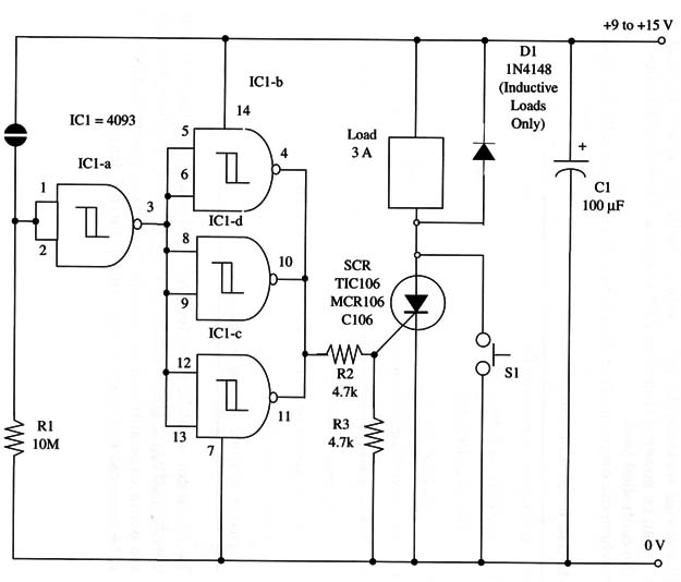
The circuit is a modification of the ART066E, where the relay is replaced by an SCR. We can power the circuit from 9 to 12 V supplies. As the SCR is subjected to a 2 V voltage when in operation (on), the load receives the power supply voltage less 2 V.
D1 is used only with inductive loads such as motors and solenoids.
R1 determines sensitivity and can be varied in a range between 2.2 and 10 M ohm. You can replace this resistor by a 10 M9 potentiometer for sensitivity control.
A schematic diagram of the Touch Switch II is shown in Fig. 1.

The touch switch uses two metal plates that are touched simultaneously with your fingers. Sensitivity is determined by R1, which can be altered in the range between 2.2 and 10 M ohm according the touch switch wires.
Long wires need low values to reduce the effect of picked-up signals that can cause erratic operation of the circuit.
The SCR must be mounted on a heatsink. Remember that this is a self-latching circuit. A single touch in the sensor turns the load on until S1 is pressed to turn the circuit off.
IC1 - 4093 CMOS integrated circuit
SCR - TIC106, C106, MCR106, or any low-power silicon controlled rectifier
D1 - 1N4148 general purpose silicon diode
X1 - Touch sensor (see text)
R1 - 10,000,000 ohm, 1/4 W, 5% resistor
R2, R3 - 4,700 ohm, 1/4 W, 5% resistor
S1 - SPST momentary switch
C1 - 100 µF, 16 WVDC electrolytic capacitor


