We describe a simple circuit which, through a touch sensor, triggers an incandescent lamp for an adjustable time interval. The incandescent bulbs are already falling into disuse, but we can still find low power types that can be used in this circuit. Unfortunately it will not work with other types of lamps.
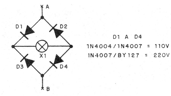
Since the circuit uses SCRs it is half-wave, ie, the lamp lights at half the nominal power, but this can be solved with a diode tip, as shown in figure 1.

The maximum recommended power is 100 W on the 110 V network and 200 W on the 220 V power grid. The ideal power is between 25 and 40 W for illumination of hallways, corridors and entrance halls.
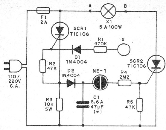
In operation, a touch on the sensor triggers SCR1 which then charges C1 to the point where the neon lamp lights up and SCR2 is triggered. After the touch is removed, the SCR1 shuts off, but the capacitor continues to discharge through R1 and so keeping the SCR off, with the lamp on.
The time the lamp stays on depends on C1.
Assembly
In figure 2 we have the complete diagram of the apparatus.

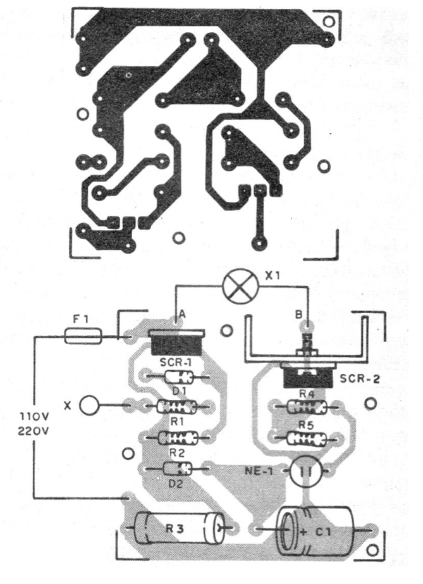
The printed circuit board for the assembly is shown in figure 3.

The SCR1 does not need a heatsink and SCR2 only needs a heatsink with bulbs of more than 40 W. On assembly, observe the position of the SCRs and the polarity of the diodes.
The capacitor must be an electrolytic for 200 V at least if the network is 110 V and 350 V if the network is 220 V. The resistors are 1/8 W with any tolerance except R3 which is 5 W.
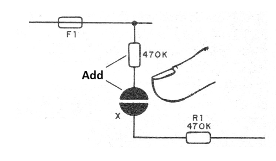
The neon lamp is common and the sensor consists of a metal plate that must be touched or two for the simultaneous touch in cases of less sensitivity, as shown in figure 4.

To test, turn the power on and touch the sensor.
If the trigger is not turned, the plug should be turned 180 degrees.
SCR1, SCR2 - TIC106B or D depending on the power grid
D1, D2 - 1N4004 or 1N4007 according to the network
NE-1 - common neon lamp
X1 - Incandescent lamp - see text
X- sensor - see text
F1 - 1 A- fuse
R1 - 470 k ohm - resistor - yellow, violet, yellow
R2, R5 - 47 k ohms - resistors - yellow, violet, orange
R3 - 10 k ohm x 5 W- wire resistor
R4 - 2M2 ohm - resistor - red, red, green
C1 - 5.6 uF to 47 uF - electrolytic capacitor, see text
Several:
Printed circuit board, power cable, wires, solder, etc.


