An inverter is nothing more than an oscillator with a power stage that powers a transformer in order to generate high voltage to excite a fluorescent lamp.
As this type of circuit does not generate a sinusoidal signal and its frequency is not 60 Hz, it is normally not suitable for powering more critical electronic circuits or devices that have motors such as shavers. However, it is perfectly suited to power fluorescent lamps.
Another possible application for this circuit is as a fence electrifier since the high voltage generated in the transformer produces a good shock.
HOW IT WORKS
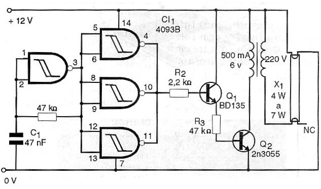
The low frequency oscillator basically consists of a 4093B integrated circuit gate used as an inverter. The frequency of this circuit is determined by R1 and C1. Depending on the characteristics of the transformer, it may be interesting to change R1 in order to obtain the frequency that provides the greatest efficiency.
The signal from this oscillator is rectangular and is applied to the three other ports on the same integrated circuit which then functions as a digital amplifier.
The signal obtained is still weak to excite a transformer so that it goes through two stages of amplification formed by transistors Q1 and Q2. These transistors are directly coupled to obtain greater efficiency and greater circuit simplicity.
The signal amplified by the second transistor is strong enough to excite a transformer, thus generating the high voltage necessary for the ionization of the fluorescent lamp.
The transformer used can be of any type with 220V primary and 6 to 12 volt secondary with current in the range from 500 mA to 1 A.
The ideal fluorescent lamp for this application is a miniature type of 4 to 7 watts when the highest performance is obtained. However, larger lamps, in the range of 15 to 40 watts, can be used with lower efficiency.
Even the lamps that no longer turn on normally in the power grid because they are very weak will work normally in this circuit because the high voltage spikes generated are sufficiently intense to cause the gas to ionize inside. Also note that, with this type of circuit, neither reactor nor starter is required.
ASSEMBLY
Figure 1 shows the complete diagram of the inverter.

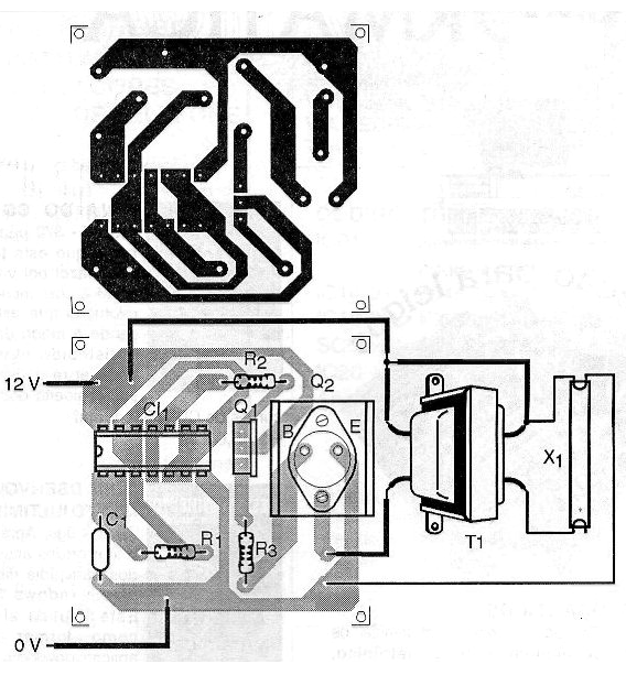
In figure 2 we have the arrangement of the components on a printed circuit board.

Note that the Q2 power transistor must be mounted on a good heat radiator. For added security, the integrated circuit can also be mounted in a socket.
The other components are all common, just noting that the resistor R3 must be at least 1 watt.
The device can be housed in a metal or plastic box but the wires that go to the fluorescent lamp must be well insulated to avoid strong shocks due to the high voltage present.
TEST AND USE
To test the device just connect it to a 12V source with at least 2A. then just make an appropriate connector for the battery or for the location of the car's cigarette lighter. The wires from the inverter to the battery must be thick and not too long so that losses do not occur.
The current drained by the circuit is in the range of 400 to 800 mA depending on the transformer used.
An interesting application for this circuit is the use of an ultraviolet fluorescent lamp (the type used in dances) that serves to check the fluorescence of rocks in mineral research.
Semiconductors:
CI-1 - 4093B - CMOS integrated circuit
Q1 - BD135 - medium power NPN transistor
Q2 - 2N3055 - high power NPN transistor
Resistors: (1 / 8W, 5%)
R1 - 47 k ohm
R2 - 2.2 k ohm
R3 - 47 ohm/1W
Capacitors:
C1 - 47 nF - polyester or ceramic
Several:
T1 - 220V primary and 6V x 500 mA secondary - power transformer - see text
X1 - 4 to 7-watt fluorescent lamp
Printed circuit board, heat radiator for the power transistor, wires, solder, etc.


