A supercapacitor discharged when connected to a charging circuit behaves like a short circuit. This requires that the sources used to charge these capacitors have special features to limit the current as well as to manage the charging process.
It is considered that as a capacitor is charged, the charge current decreases, thus reducing the speed of the process. All of this leads to the need to use appropriate circuits in any application in which a supercapacitor must be charged.
In this article, we describe the use of Maxim's MAX17701, based on the datasheet itself which can be accessed at: https://br.mouser.com/datasheet/2/256/MAX17701-1888136.pdf. We also inform you that Maxim provides an evaluation kit through Mouser Electronics.
Description:
The MAX17701 is a component of Maxim's Himalaya series of voltage regulators, power modules and chargers. It is a synchronized stepdown regulator that can operate with input voltages from 4.5 to 60V.
It is possible to charge a supercapacitor with a constant current with an accuracy of 4%. After charging, it is maintained in the condition of no external charge with an accuracy of 1%.
The output voltage can be programmed between 1.25V and 4V below the input voltage.
The device uses an external MOSFET N to provide protection against short circuit, being connected on the side of the power supply. Its purpose is to avoid the discharge of the supercapacitor.
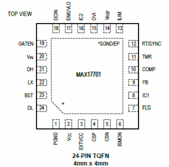
The MAX 7701 is available in a 24-pin TQFN enclosure measuring just 4 x 4 mm, as shown in figure 1.

In the datasheet, designers can find a complete description of the pin functions. In figure 2 we have a typical application circuit, with emphasis on the sensor resistor that allows the control of the load and the external protection MOSFET.

In the datasheet we have the entire component calculation process for the desired application. We also have performance graphs and tables that can be useful.
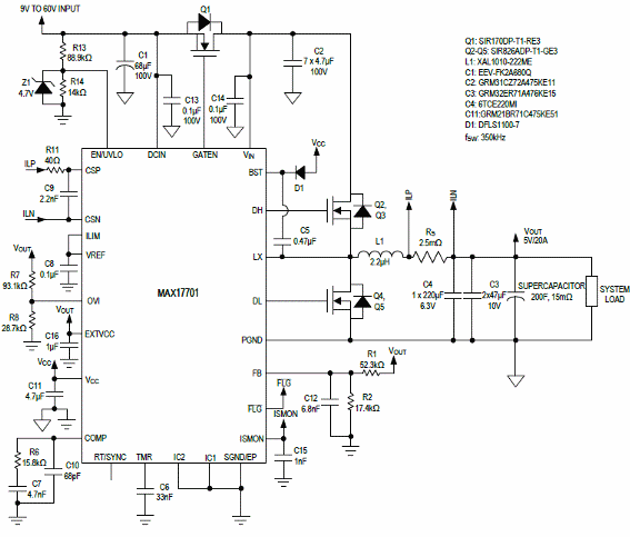
But, for those who want a ready-made solution, we have the design of a supercapacitor charger with a current of 20A using the MAX17701. This circuit is shown in figure 3.

This circuit is for a specific application in which a 20F supercapacitor is charged with 5V. The input voltages of this circuit can be between 6.5 V and 60 V.
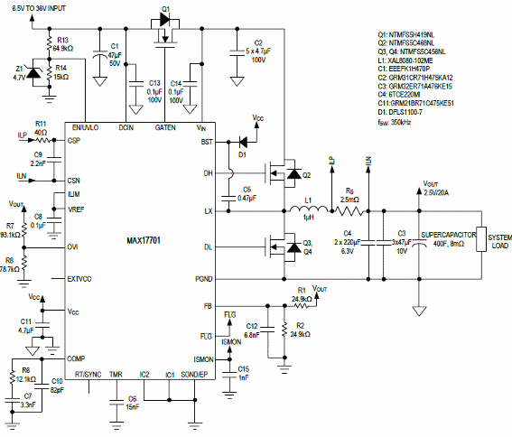
Another charging circuit for a 40F supercapacitor is shown in figure 4.

The input voltages for this circuit are indicated in the diagram and observations on the types of components used are given.
Among the applications for this component, Maxim suggests energy storage systems, industrial security, portable medical equipment, automation etc.
Some important information about the MAX17701 is given below:
- Load current accuracy: +/- 4%
- Accuracy of the regulated voltage: +/- 1%
- Input voltage range: 4.5 to 60V
- Adjustable switching frequency: 125 kHz to 2.2 MHz with external clock synchronization
- Output overvoltage protection
- Programmable load current


