ART1952S
Damped Twin T oscillators can faithfully imitate percussion instruments and thus work as a basis for interesting projects like this.
An oscillator driven by a sensitive input amplifier can produce the sound of a gong, bell or similar instrument by simply touching a sensor.
The sensitivity is very high, which means that even a very soft touch can trigger the circuit, and if you connect the output to a powerful amplifier you will have a huge gong or bell ringing at full power.
The base of the circuit is a Twin T oscillator which produces sine waveform signals whose frequency depends on the elements of the feedback or Twin T circuit.
The values of the components of this Twin T need to maintain a well-defined relationship between them.
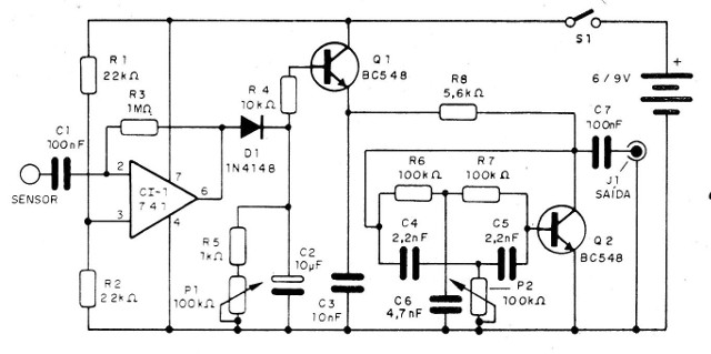
Controlling the feedback of this circuit through the potentiometer P2 in the main diagram, we can take the circuit to a critical operation and with this the production of damped oscillations, that is, oscillations which decrease in intensity until disappearing.
These oscillations, when amplified and applied to a loudspeaker, generate sounds similar to what we get when we hit glass or metal objects which resonate for a certain time, like the sound produced when we hit a bell, a gong, a glass or a metal bar.
With the choice of the appropriate values for the Twin T capacitors, we can perfectly imitate the sounds of these objects by simply adjusting P2 accordingly.
As the Twin T oscillator is somewhat unstable to obtain a critical adjustment, in our circuit we have added a second time delay to guarantee an extension, without the oscillation remaining "locked" indefinitely.
In our circuit, this is achieved by Q1 which, from the stimulus at its base obtained by the C2 charge, controls the Twin T feed precisely, for an interval set at P1.
The touch stimulus signal comes from a type 741 operational amplifier.
This signal is nothing more than the network noise that is normally picked up by our body and which is transferred to the circuit when we touch a sensor, via C1.
The operational gain in this function is basically given by R3 and can be changed. Smaller values allow a reduction in sensitivity if there is a tendency to erratic circuit triggering.
Values between 10 k ohms and 4.7 Mohms can be used in this project. Even a third potentiometer can be added in this function, depending on the application that the reader has in mind.
The audio signal obtained at the output of the oscillator is too weak to drive a speaker, so we need a good external amplifier.
In the case of lower sounds, like the ones from gongs and bells, as they have a very low frequency, the best results are obtained with sound systems which have heavy speakers.
The supply of the circuit with a 6 V or 9 V cell battery is possible thanks to the low current consumption of the unit.
In Figure 1, we have the complete diagram of our device.

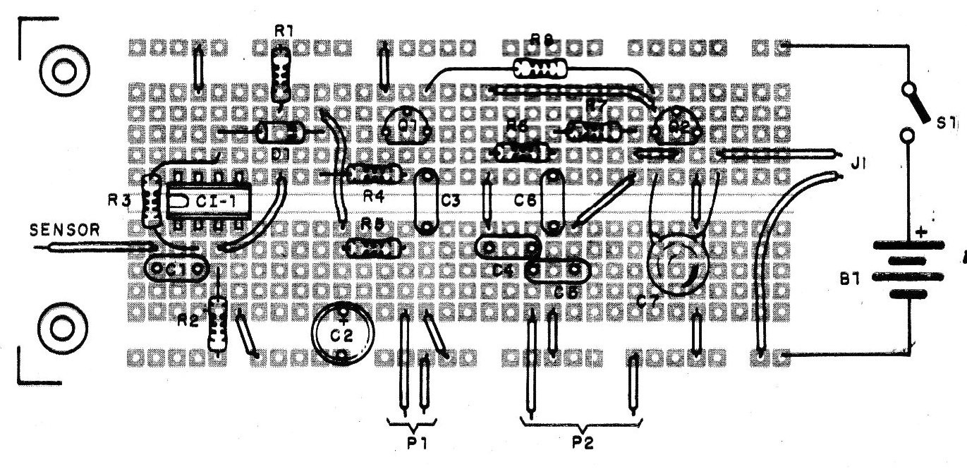
In Figure 2, we have the arrangement of the components on a universal board or breadboard.
For board mounting, we suggest using a socket for the integrated circuit. Transistors can be replaced by equivalents.
The D1 diode can also be replaced by equivalents such as 1N4002 or 1N914. P1 and P2 can be trimpots for mounting on the breadboard or potentiometers, depending on the application.
The electrolytic capacitors are for 12 V or more and the rest of the capacitors are polyester or ceramic. The Twin T capacitors can be chosen according to Table 1.
| C4/C5 | C6 | Sound Type |
| 22nF | 47nF | low-pitched (gong) |
| 10nF | 22nF | mid-pitched(bell) |
| 4.7nF | 10nF | mid-pitched(small bell) |
| 2.2nF | 4.7nF | high-pitched(triangle) |
| 1.2nF | 2.2nF | very high-pitched(glass) |
The sensor can be the simple tip of a stripped wire or a metal plate with no more than 5 cm on its side. Bigger plates can cause instabilities in the circuit as well as wires longer than 1 meter. In this case, shielded wires must be used.
To prove it, just connect the circuit output to a medium volume audio amplifier. Activate S1 and touch the sensor while adjusting P1 and P2. By setting P1, we have the timing, and by setting P2, we have the damping which allows us to imitate the desired sound.
An interesting possibility for the designer is to add a switch that commutes the values of the Twin T capacitors.
If an external power supply is used, it must be 9 to 12V with at least 50 mA and excellent filtering so that no loud snoring occurs in the speaker.
Do not use a power supply without a transformer as the activation is done directly by touch.
IC-1 -741
Q1 and O2 - 80548 or equivalent
D1 - 1N4148 or equivalent
P1 and P2 - 100 k ohms - potentiometer or trimpot
B1 - 6 or 9 V - cell batteries or battery
S1 - Single switch
Resistors: 1/8 W
R1 and R2 - 22 kohms
R3 - 1 Mohms
R4 - 10 kohms
R5 - 1 kohms
R6 and R7 - 100 kohms
R8 - 5.6 kohms
Capacitors
C1 - 100 nF - ceramic or polyester
C2 - 10 uF x 12 V - electrolytic
C3 - 10 nF - ceramic or electrolytic
C4 and C5 - 2.2 nF - see text - ceramic or polyester
C6 - 4.7 nF - see text - ceramic or polyester
C7 - 100 nF - ceramic or polyester


