To know more about integrated circuits see ART203E
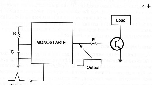
In the monostable mode, once triggered, the circuit produces a signal during or after a time interval triggering something or controlling something as suggested in Figure 1.

In the unstable mode, the circuit generates a square signal with frequency dependent on some external components, normally an R-C network as shown in Figure 2.

Symbol
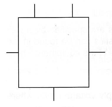
Figure 3 shows the symbol used to represent this function. The ICs of this family are found in DIL cases and others.

The 555
The most common of the timers is the 555 that can be found with manufacturer designations such as NE555, TLC7555, LM555, and MC555.
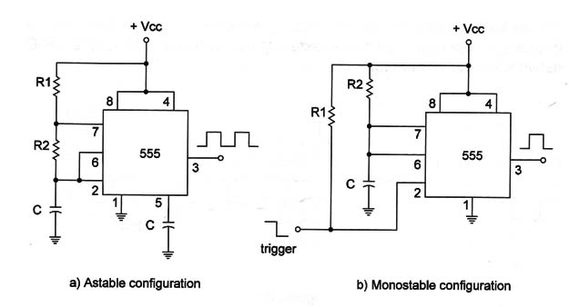
This integrated circuit can operate in two modes: unstable and monostable depending only on the way some external components are connected as shown in Figure 4.

The bipolar version (where the internal transistors are bipolar types) can provide time intervals up to one hour and oscillate in frequencies up to 500 kHz.
A version using JFET transistors (TLC7555) offers larger time intervals and produces higher frequencies with lower current consumption. The meaning of 555 to electronics can be evaluated by a recent report that said that more than 1 billion units of this device type were sold since it launched.
Specifications
The timers in the form of integrated circuits are specified by a part number just as others. The electrical characteristics can be found in the manufacturer’s documentation or the schematics of the equipment where they are being used.
The main electrical specifications are:
A. Power supply voltage-the given power supply voltage range where the circuit can operate.
B. How to calculate the time interval or frequency-In the applications, the external components (R and C) determine the operation frequency. A formula or curve allows the designer to find the correct value for the components to any application.
C. Output current-This is an important piece of information, as it says what can be controlled from the IC and how it can be done. In some cases, a transistor stage must be used to control something with a large current consumption
D. Operation modes-Many timers have different operation modes. They are given in the specifications with information about the way the external component must be connected to perform.
Where they are found
There are many small devices found in electric installations that are based in timers like the 555, TLC7555, and many others. When you press a pushbutton in the wall and the lamp stays on for a certain time interval, most likely the circuit controlling this includes a timer integrated circuit like the 555 or one of the same family.
Testing
As in many other integrated circuits, there isn’t a special procedure to test them. Any integrated circuit is a different circuit and specific procedures should be developed to make an effective test. The best way to know if the IC is good is by reading the voltages at its pins. Start with the idea that all other components are good, and compare voltages with specifications or indications in a diagram.


