
ART1292S ART5375
Pio José Rambo
If we were to go through again everything, we have already disregarded by sending it to the trash or the scrap yard, I am sure that several items would deserve not to have this unfortunate fate. This is the case with burned transformers. We have thrown so many in the trash that, if they were piled up, we might not be able to carry them, and such would be the weight of the package.
Aiming at the reuse of these discrete, yet indispensable elements in most of our projects and present in almost all commercial circuits, we have done this work.
Almost all electrical engineering magazines have already addressed the subject of transformers but always surrounded by many calculations and little practical content. We intend to do the opposite, that is: to outline the complete practice on transformers starting from a burnt-out one, acquired solely from the daily needs and conflicting constraints of a workshop. For the calculation of turns (which will be addressed later), we will have only one number which is the constant (essence), an essence extracted from all other calculations. Thus, with a single number that is easy to memorize, we will calculate any type of power transformer regardless of its current or power.
HOW TO DISASSEMBLE TRANSFORMERS
This first subtitle seems aimed at novices and beginners, however, many transformers are resin-coated or varnished to the point where it seems impossible to remove the core. The necessary tools are: a pocketknife, a steel blade (flat spring), a hammer, and a vise.
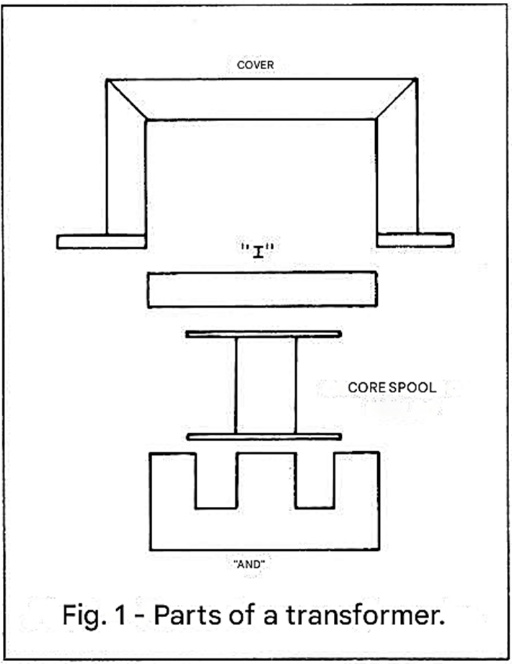
After removing the transformer cover (Figure 1), take the pocketknife and loosen the first three blades ("E") from one side of the core. Detach only the side blades (edges), as the center (the core itself) is unreachable. Now remove the "I"s from the loose parts (Figure 2). Once this is done, place the transformer on the vise, supporting the block of metal that has not yet been loosened. Insert the steel blade into the second "E" and tap with the hammer until it comes out of the core.
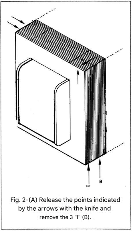
Usually with a loose plate (an "E" shape). With time, this operation will become easy to perform (Figure 3).
Note: the steel blade cannot be wider than the center of the reel so that it can pass through it.
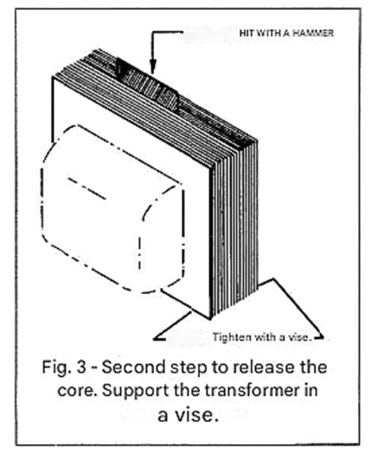
Generally, with a loose plate (an "E" removed), it is easy to disassemble the rest of the plates, simply by removing plate by plate with a knife.
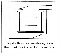
To open "F" cores (types of audio output transformers) the procedure is much easier: tap the core with a hammer and you will feel the reeds moving. Do not hit too hard so as not to crush the reeds. After this operation, wedge the loose parts of the first reed with a screwdriver and force it out (Figure 4).
A third type, even easier to distinguish, is the vertical output type and the choke transformer. These two types (some audio outputs are also like this) have all the "I" connectors aligned on one side and the "E" connectors aligned on the opposite side.
HOW TO REMOVE BURNED WIRE FROM THE CORE
This operation is quite easy when you have a sharp knife. Start by removing the paper and stickers that finish the transformer. Then - when the secondary is wound over the primary - unwind it by hand. Usually there aren't many turns, and it's not advisable to reuse the secondary wire because its varnish may have been affected by the heat from the transformer burning. Now take the knife and cut the primary in layers. Loosen the cut part of the wire with the knife and strip the cut part by hand or with pliers. Proceed in this way until you remove all the wire (Fig. 5). When you get the hang of it, you can completely "clean" a core in a matter of moments.
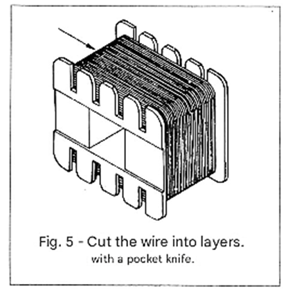
Do not leave any wire residue on the spool, and if the core has overheated to the point of melting some wire turns into the plastic at the bottom of the form, apply a layer of adhesive tape before starting the new winding.
MATERIALS NEEDED TO MAKE TRANSFORMERS
We will only address the part about power transformers, since the other models (vertical output, audio output, drivers, etc.) generally have their winding dimensioned for the model they are intended for, and their construction is quite critical. However, if necessity forces you to assemble a different transformer (and I cite as an example the vertical output transformers of Admiral-type televisions), you must count the number of turns and faithfully follow its assembly as per the original. This care must also be taken regarding the process of turns to be wound by insulating layer after layer.
To manufacture power transformers – from 150 mA to 5 A and voltages between 3 and 50 V – we will need the AWG gauges indicated in Table 1. The most useful spool for this purpose is the soldering spool (type "Best"). This spool holds half a kilogram of wire of any gauge starting from 30 AWG. Below this gauge, the quantity should be gradually reduced: up to 25 AWG wire, 400 grams fit, and below this, only 300 grams to avoid overloading the spool. Ideally, you should have a little of each type of wire mentioned in Table 1 to maximize the reuse of burnt-out transformers. In addition to the thread, you will need a roll of 3.2 cm (1/4 inch) wrapping tape, a roll of adhesive tape (like "Durex"), cardboard (like a shirt box), scissors, a ruler, a calculator, and a sheet of cellophane or plastic for finishing. Furthermore, you will need at least 6 different colors of wire and insulated radio cable. As for the winding machine, there are simple yet efficient models available on the market at very affordable prices. Usually, a single-counter machine with a zeroing device is about the same price as these complete winding machines with a built-in counter.
HOW TO CALCULATE WINDINGS
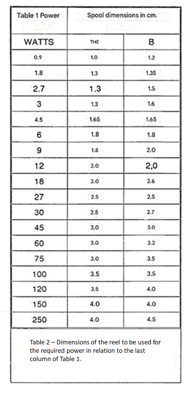
Since this article is designed solely to cover the practical aspects of transformer manufacturing, instead of calculating the core size required for the desired power, we will provide an average of pre-calculated measurements, which practice has shown to be universal in relation to bobbin size versus power handling. This summary is in Table 2. Obviously, there will be many variations in the bobbin measurements mentioned above, depending on their origin and purpose. However, the measurement "A" (Figure 6) of the bobbin serves as a rule of thumb for the desired power, and this value varies very little commercially.
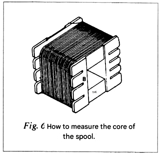
The measurement of the magnetic field encompassing the core is technically performed on the lamination bundle at the point where the laminations penetrate it. However, we can obtain measurements identical to those of the air gap if we base them on dimensions A and B of the bobbin (Figure 6). Using a ruler, measure the points as indicated in the figure, carefully and accurately noting the results of these measurements.
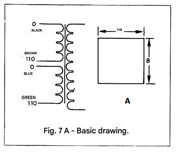
Note that a measurement difference of 0.5 mm (half a millimeter) can result in more than 100 turns in the calculation of the primary winding of a 500mA transformer. Once the core is dimensioned, note everything as suggested in Figure 7A. It is important to dedicate a notebook or notepad solely for these notes, so that when rewinding a transformer identical to one already processed, we can refer to it, avoiding having to recalculate these transformers.
The constant to be applied to find the exact number of turns is 266.4. This is not a number chosen at random. It comes from the sum of all the calculations involved in making transformers so that the windings can "withstand" the current and voltage for a given core, without overheating or burning out. And this number is used to calculate the ratio of any voltage transformation in cores with 10,000 Gauss of magnetic flux (this measurement is standard for our air gaps). Theory aside, this number is responsible for more than five hundred transformers of all sizes, working perfectly.
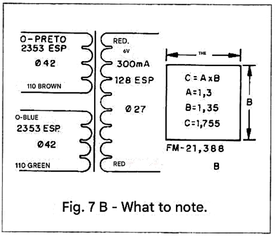
Figure 7B shows an example of the calculation of a transformer with a primary of 2 x 110 V and a secondary of 6 V/300 mA. This will be done as follows to arrive at this result.
Only one formula needed:
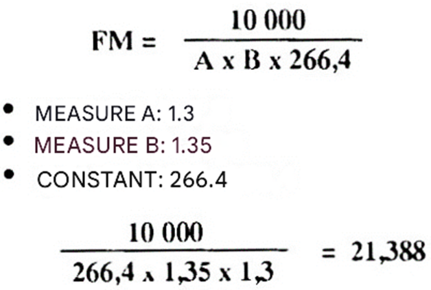
The multiplicative factor (MF) will be: 21.388 21.388 x 110 = 2352.68 - round to 2353 turns 21.388 x 6 = 128.328 - round to 128 turns.
The calculation above can always be done when we want to manufacture common transformers that will not be permanently connected to the electrical grid. In the case of transformers that will always be connected (like those in clock radios, VCRs, etc.), we will have to add 10% for core conduction losses so that it can comfortably withstand this requirement. In our calculation, this loss will be represented by the constant 1.1. Below is the same calculation as the transformer above, with the constant included:
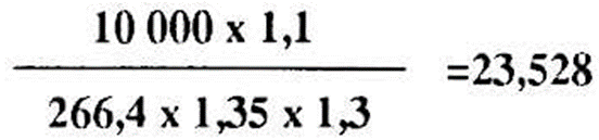
23,528 x 110 = 2588 turns for each 110 V winding
23,528 x 6 x 1.1 = 155 turns for each 6 V winding
We can see from the explanation above that a transformer for constant use results in a considerably larger number of turns and wire than one for intermittent use. I emphasize in this aside that commercial transformers are generally calculated and dimensioned for intermittent use. Once we have noted the number of turns for each voltage value and know the wire gauge to be used (see table 1), we can manufacture the transformer itself.
Table 1 shows all the characteristics regarding which wire gauge to use according to our needs. It is good to remember that the first two columns, titled 'PRIMARY', provide the AWG gauges for 0-120-220 V type windings. For the 2 x 110 V mode, we will use the wire gauges from the second column titled "220 V" since at 110 V the two windings will be in parallel, thus supplying the required current demand with a wire of half the thickness. In truth, making the 2 x 110 V mode in the primary is much more convenient and faster since there will be no change of wire gauges during the primary winding.
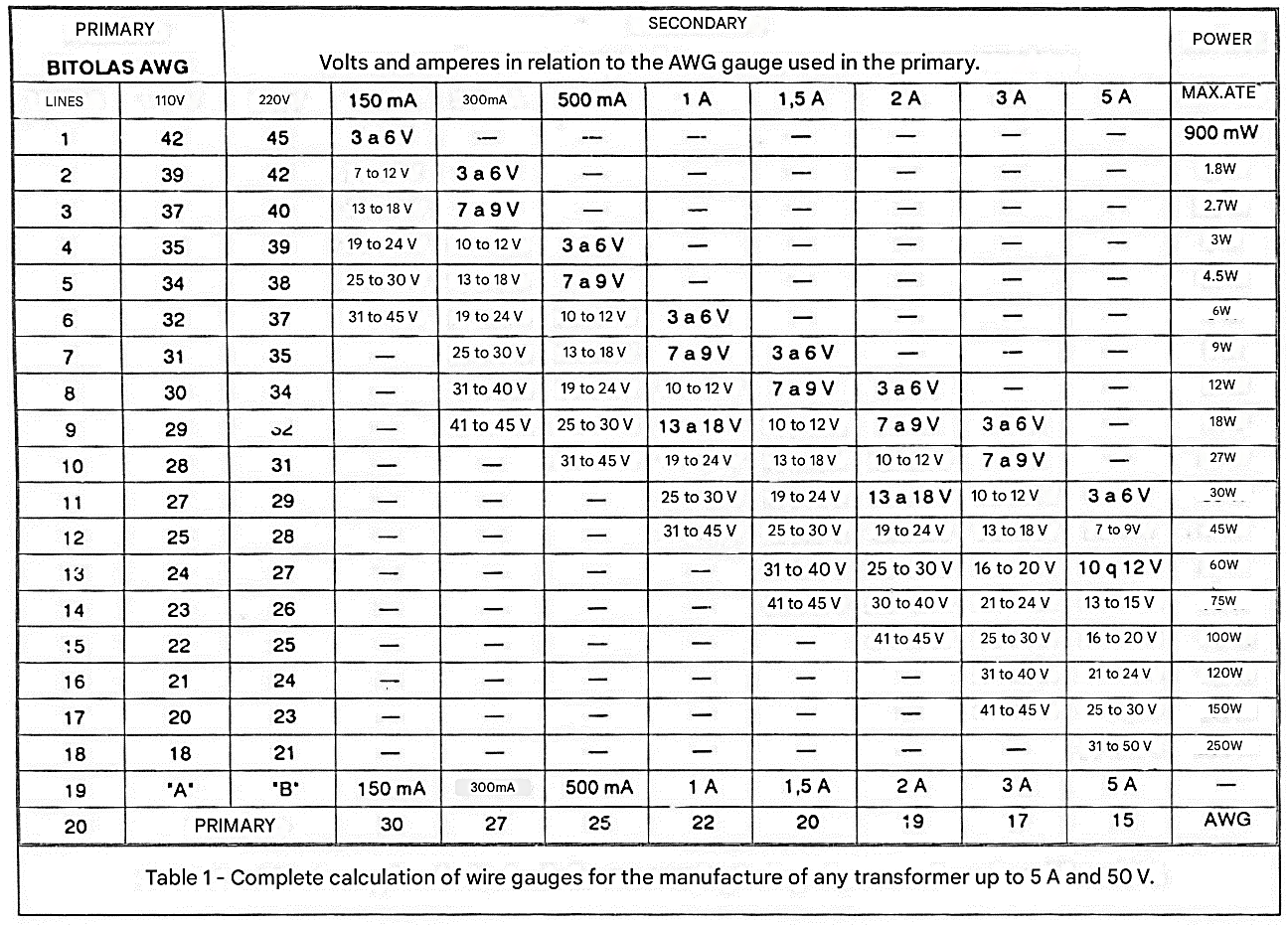
Then our transformer will look like this: for each 110 V winding we will use 42 AWG wire (2nd row, 2nd column of table 1), which corresponds to a 6 V/300 mA transformer. In addition, the wire to be used in the secondary will be 27 AWG (last row, 4th column of table 1). Our transformer will have 1.8 W (2nd row) and according to table 2 this is equivalent to a core of 1.3 x 1.35.
HOW TO ASSEMBLE THE TRANSFORMER
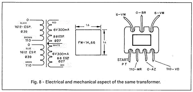
For each winding made, leave approximately 5 cm of wire, to which the small wires that will make electrical contact in the circuit will be soldered. As a practical example, let us assume that a 6 + 6 V/300 mA transformer has been wound. Figure 8 shows its appearance. Make 6 small wires in colors that indicate how the "wire" was wound, namely: dark colors for the two beginnings (0 V) of the 110 V windings and light colors for the two ends (110 V). Orange or red for the two "hot" wires of the secondary and any other color for the center tap. The average length of these wires is around 15 cm. cut them to this size and strip 0.5 cm from one end. Take the carbon paper and cut two pieces of length equal to size B in the example above and, in one of them, make eight holes and in the other 6 (Figure 9). As shown in this figure, insert the wires from the exposed parts into these holes.
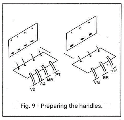
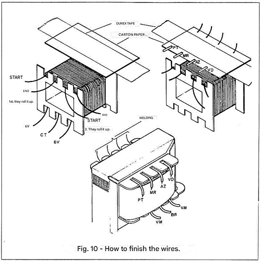
Once this is done, attach these bundles to the coil (1 on each side), noting that the winding must be insulated with carbon paper in these parts (fig. 10). Now strip the turns from the windings and solder them to the bare ends of the wires, observing their colors. Then, as the solder hardens these ends, bend them in the direction of the wire exits. This will provide great mechanical resistance at the terminals, preventing any wire from accidentally being pulled out of place. Apply masking tape the width of the core over the entire winding and finish with cellophane paper. Technically, there should be enough space left on the core for all these adhesive layers.
Once the core itself is finished, we still need to put back all the "Es" and "Is" that will form its magnetic field.
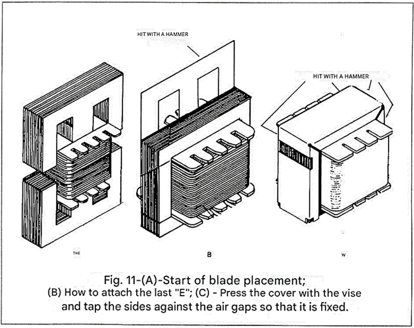
Leave the “Is” for the end of the process. Start by placing only one 'C' on one side, in the same direction as the casing that will hold the transformer. Then, in the opposite direction to the first lamination, place two “Es”. Continuing, insert the “Es” always-in pairs, namely: one pair from top to bottom, then a pair opposite to this one. When there are 3 pairs left (6 pieces), the space on the core will begin to become restricted for placing all the laminations. Separate the pieces and place two more pairs, exactly as you have been doing. Now, place only one lamination, which will be the last in the sequence. The remaining “E” usually needs to be hammered in, which is a very delicate process. To avoid crossing the laminations, insert the beginning of this small plate between one of the last pairs that were placed and previously separated for this purpose. Carefully tap the central body of this lamination with the hammer until it penetrates completely, taking care of the linearity of the descent of this last 'E' on the sides of the transformer. This detail is important because if the lamination descends crookedly into the core, it can cut the plastic in the center of the bobbin and scratch or even sever some turns of the first winding. This entire process is shown in Figure 11. If the reader does not proceed in this way when placing the core, they will probably have leftover pieces of some of the laminations that were originally part of this core.
Having replaced all the laminations, we must insert all the "Is". This process is easy and does not require further explanation. It is only worth remembering that if the reader does not want to varnish the transformer, do not place the "Is" of the first and last laminations. The Gauss to which they respond is so minuscule that it is not worth leaving them vibrating and heating the transformer.
The cover for securing the transformer is easily installed using a vise: clamp the cover against the air gaps and tap it against them with a hammer to secure it and prevent vibration of the air gaps.
This process is shown in Figure 11C.
PRACTICAL EXAMPLES
When you want to wind more than one secondary winding, Tables 1 and 2 perfectly explain how to proceed. However, since this article aims to be practical, we will give some calculations for transformers with more windings on the secondary below. I want to build a transformer with a primary of 2 x 110 V and two secondaries of 12 V x 500 mA (Fig. 12).
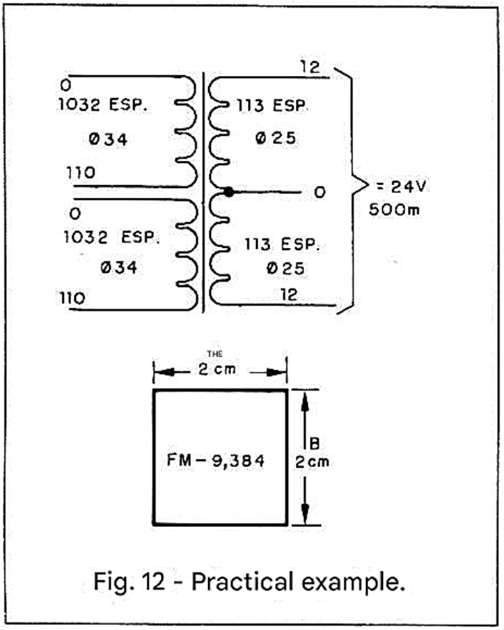
In Table 1, in row 8B and column 32 of the secondary, we have a 24 V (2 x 12 V) 500 mA transformer, using 34-gauge wire for 220 V (2 windings of 110 V) and its power is 12 W. In the same column, in row 12 and the penultimate row, we have the indication of the mill amperage we want, that is, 500 mA. In the last row of this same column, the AWG gauge for this current demand is indicated. In this case, the wire used will be 25 AWG, which will withstand the consumption of 500 mA.
12 W in Table 2 is equivalent to the field of a "2 x 2" core. With this data, provided a "2 x 2" core is provided, we will calculate the constant (the multiplicative factor - FM) for this core:
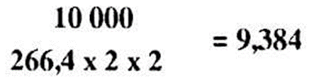
Multiplicative factor = 9.384 110 x 9.384 = 1032.24 = 1032 turns for each 110 V. 12 x 9.384 = 112.608 = 113 turns for each 12 V. 4 25 (j) - Means AWG section.
I need a transformer that is always connected to the mains (apply the constant 1.1) and that has a single 110 V primary and three secondaries, namely: a 15 V x 1 A winding for the amplifier, a 5 V x 500 mA winding for a logic circuit, and two 24 V x 150 mA windings for a symmetrical preamplifier. This example is graphically represented in Figure 13.
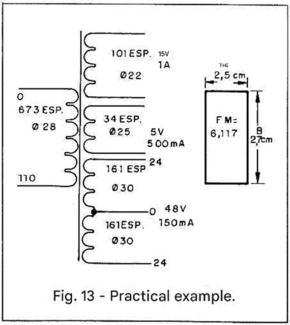
To calculate the wire gauge used in the primary, we first need to determine the total power that this transformer will distribute. From Table 1, it is easy to verify this: 15 V x 1 A = 18 W (9th row); 5 V x 500 mA = 3 W (4th row); 24 V x 150 mA = 3 W (4th row); However, since there are two 24 V, 150 mA windings, the power assumed by these windings will also be double: that is, 6 W. Adding everything up: 18 + 3 + 6 = 27 W. This is the total power required by the secondary. The wire gauge we will use for the 110 V winding will be 28 AWG (10W line = 27 W).
With this power, we deduce from Table 2 that the minimum dimensions of the core bobbin should be 2.5 cm x 2.5 cm, but we chose 2.5 x 2.7 for greater operating clearance. Calculation of turns:
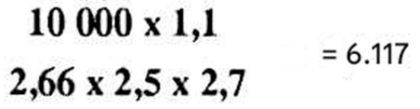
Multiplicative factor: 6.117 110 x 6.117 = 672.87 = 673 turns for 110 V. ☐ 28 AWG
15 x 6.117 x 1.1 = 100.93 = 101 turns for 15 V. ☐ 22 AWG
5 x 6.117 x 1.1 = 33.64 = 34 turns for 5 V. ☐ 25 AWG
24 x 6.117 x 1.1 = 161.48 = 161 turns for 24 V. ☐ 30 AWG.
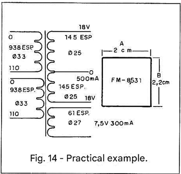
If we need to repair a transformer whose secondary voltage we don't know, we can find it by proceeding as follows: we count the turns that occupied the secondary (secondaries) of the transformer; then we calculate the cross-section of the core (A x B). As a third step, we divide the number of turns found by the result of the core area (A x B). This result is the voltage that the core delivered. Note that transformer manufacturers may use pre-established templates for the various windings of different voltages versus different amperages, and the voltage value found is not always exact.
Our method always consists of assuming the commercial value closest to this result. A difference of one volt, depending on the purpose, does not alter the final result of a transformer. Example of an unknown transformer: I need to wind a transformer for an amplified speaker box under repair, for which I do not have the schematic and I have no idea of the voltages it needs to function perfectly. The primary winding has two windings for 110 V and two independent windings in the secondary, one with a center tap. See Figure 14. The total number of turns in the 19th winding is 145 and in the last winding is 61 turns of 27 AWG wire. The core measures 2 x 2.2. Multiplicative factor: 8.531.
Calculation:
61 / 8.531 = 7.15 V - Closest commercial value = 7.5 V.
145: 8.531 = 16.99V - Closest commercial value = 18 V
110 x 8.531 = 938.41 = 938 turns for 110 V. From table 2 we have that a 2 x 2.2 core can be occupied by a transformer of up to 18 W. By our calculation, 18 V by 500 mA (row 7, column 3 - table 1), is equivalent to 9 W. Since this transformer has 2 windings of 18 V, we will have in the end, 18 W (9+9 VV).
Adding to this value the power required by the 7.5 V/300 mA winding (row 3, column 2 - table 1), we have another 2.7 W. Thus, our transformer will have to handle a total of 21 W (20.7 W), which requires 31 gauge wire in the primary (the closest between 18 and 27 W in table 1) for the 110 V windings. The original wire wound was 33 AWG, and a thicker gauge would not fit in the core of this transformer with the two secondaries. Therefore, the original gauges were chosen. Ideally, a larger core should have been used for this component to perform its role perfectly.
In the example above, the most important thing was to discover the voltages that the device required for its perfect performance. And, in this way, we can obtain any unknown voltage in any type of assembly and in any transformer. Another example of an unknown transformer: We have a receiver with a short circuit in its primary winding. Its core measures A = 3 cm and B = 3.5 cm. It has a 110 V winding and a 220 V winding on the primary. On the secondary winding, it has 3 windings, one of which is center-tapped (Figure 15).
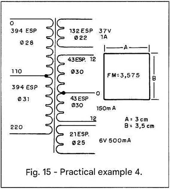
We should note that the last winding, which has 21 turns, was used to power the three backlight lamps of the dial. Since the lamps are 6V, this winding will obviously have 6V. To verify our multiplicative factor number found in the calculation above, we will check:
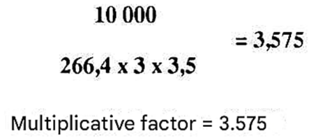
21 turns divided by the MP of 3.575 will equal 5.8V, which corresponds to approximately 6V. As previously mentioned, transformer manufacturers may occasionally use pre-established standard numbers, causing our numerical results to sometimes differ from the calculation of the original transformer. However, this tolerance will always be small, on the order of 5%.
The penultimate winding with a center tap has 2 times 43 turns. Calculating: 43 : 3.575 = 12.02 V = 12 V. Since it will be with a center tap, it is 2 times 12 V. The third-to-last (first) winding has 132 turns. Thus: 132: 3.575 = 36.92 = 37 V.
To rewind the primary, we simply multiply 110 and 220 by the multiplicative factor 3.575. This results in 394 turns for each winding. Here we should note that half of the 220 V already circulates in the 110 V winding, so it is not necessary to wind twice the number of turns for twice the voltage. See the figure again. 15.
Besides all this data, there is still a small drawback to the full versatility in transformer manufacturing: how to obtain a core for a transformer that must withstand a certain current and voltage (previously planned) so that it fits in that little space left inside the box, after all the circuits have been installed? - or, how to wind a transformer that has a cardboard core? Or, how to rewind a transformer of a special size, whose core melted when it burned out?
It is a shame to throw away those shiny "Es” and "Is”, free of any oxidation! I must admit that these questions led me to a very practical solution. Thus, it is possible to use all the cores and the idea can create special types of transformers depending on the need and the space they will occupy. The material for making the cores is also plentiful in workshops. It consists of a heat-resistant plastic, with a special texture and great mechanical strength: it is neither too rigid nor too soft to the point of giving way. What kind of plastic is this? TV back covers! That is right! Instead of throwing them in the trash, cut off the smooth, straight parts and save them.
HOW TO MAKE THE SPOOL
Take the "E" bundle from the core that needs a spool. Align them all into a block shape. Clamp them in a vise, and wrap adhesive tape around the central leg (at the height of the "X" in Fig. 16) to keep it inflexible. Take your measurements. Now observe Figure 16: we will need two identical pieces of size A x C.
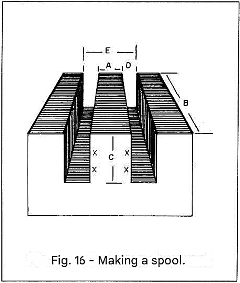
Two identical pieces of size B x C will also be needed. Plus two sides for the spool, the size of B + 3D by E. This means that these last two pieces will have the length of measurement B plus 3 times the measurement of D (average height of the spool). And the width of these two pieces will be E.
Example:
A - 1.90 cm
B - 2.15 cm
C - 2.80 cm
D - 0.95 cm
E - 3.80 cm
Thickness of the plastic material: 0.15 cm.
The two "X" pieces (fig. 17) will have a width equal to 1.9 cm ("A") and a height ("C") equal to 2.80 cm minus twice the thickness of the material we will use because of the two "W" sides. Since the thickness of the plastic in this prototype is 0.15 cm, we must subtract this value twice, that is, 0.30 cm. Then, the "X" pieces will be 2.80 cm minus 0.30 cm, equivalent to 2.5 cm in height.
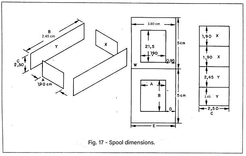
The two "Y" pieces will have a height of 2.45 cm (B minus 2 times the thickness of 0.15 cm), to overlap the edge of C.
Their height will be equal to the height of the "X" pieces (2.50 cm).
The "W" pieces will be 2.15 (B) + 3 x 0.95 (3D) = 5 cm. Each "W" piece will then be 5 cm x 3.80 cm (E). To mark the window on the sides of the reel (which is equal to the measurement of A x B), find the center, draw two diagonals and from there make the window perfectly centered on the piece. Then, make a hole and carefully cut with a small saw (one of those bow saws for manual work on plywood) what was traced. With metal scissors, cut out the remaining traced parts (which will form the sides). Never forget to increase the thickness of side C in part B by millimeters. Also, remember to decrease the thickness of both sides of the parts that will form the spool by millimeters.
Remove the core from the vise.
Also, remove the adhesive tape that held the blades in place. Insert the first "W" side. Apply a generous layer of plastic solder (the type for plastic pipes, suitable for any type. However, Polytubes plastic solder has shown greater mechanical resistance) around the window and assemble the 4 pieces that will form the reel on top. To keep these pieces firm until they are welded, join them with adhesive tape. Seal all joints well with plastic solder. Finally, seal the window on the remaining side and press it against the reel pieces. Check that the material does not exceed the height of the "E"s. If it is level, place a weight on top of the reel and let it dry for 24 hours. Carefully remove the "E"s and let the reel dry for another two days before subjecting it to pressure.
Another example:
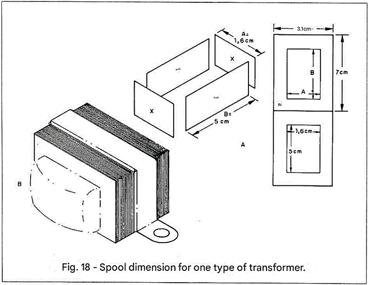
I need a transformer with a maximum height of 500 mA transformers. The length does not matter. It needs to supply 2 x 18 V/250 mA on the secondary, plus a 1.8 V/150 mA winding to power an LED. It will be continuously connected to the mains. The solution is to take three 3 W cores and make a bobbin that can house these three cores. The result of the bobbin is as shown in Figure 18A and its final appearance as shown in Figure 18B.
A=1.6 cm / B=5 cm / C=2.4 cm / D=0.75 cm / E=3.1 cm. Thickness of material B = 0.10 cm. Other parts = 0.15 cm.
X dimensions: 1.6 cm x 2.1 cm
Y dimensions: 5.3 cm x 2.1 cm
By proceeding in this way, we can manufacture any type of transformer and spool.
FORM USED FOR THE DEVELOPMENT OF THIS PROJECT
• Constant to determine the number of turns:

• AWG gauge of the Secondary:

Application of the AWG table to convert the section in mm² to AWG.
• AWG gauge of the Primary:

Calculation of core size in relation to power (Table 2):
S = 1.2 W
CONCLUSION
Through this work, we can note several important points to "unmask" the infamous transformer.
And, although this work appears virtually practical, we should not expect to know everything in the execution of the first project.
Practicality in any task is acquired through repetition of what we learn, and this repetition opens new horizons, making us fearless explorers of new elements, adding to all the points we already knew.


