In mechatronics and in many associated applications like robotics, internet of things (IoT), wearable, etc. the microcontrollers occupy a prominent position consisting of the "brains" of the circuits, since they gather the functions of intelligence, memory and control in a very small space.
Thus, when we move from simple didactic and experimental projects such as those used in technology courses (STEM) to a next stage, the inclusion of the microcontroller can not be overlooked.
For this reason, we include in our site basic information on the use of microcontrollers in mechatronics projects, highlighting how to use them.
We can not go far because much more than simple components, microcontrollers bring together a myriad of characteristics and behaviors, and can be found in a variety of types and shapes that differ in what they can do and where they can be used.
This series of articles therefore serves as a basic guideline for those intending to use microcontrollers in robotic, mechatronic and artificial intelligence projects, and interested parties should study the target types through appropriate literature.
What is a microcontroller?
The integrated circuit gives us the idea that it is possible to assemble in a single enclosure or component a complete circuit which performs a certain function. For example, as we have already seen in this book, we have integrated circuits which act as amplifiers, voltage regulators, logic functions, etc. (Figure 1)
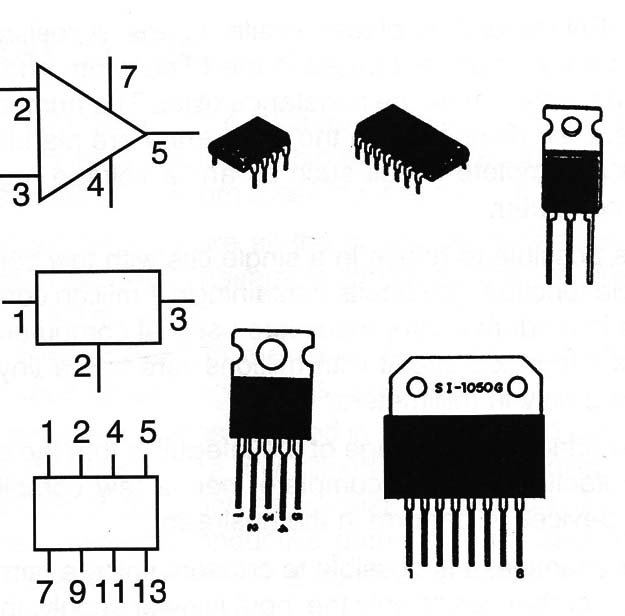
However, each type of integrated circuit performs a unique function which is determined by the arrangement of the components therein and their interconnections at the time they are manufactured.
The idea of the microcontroller is a bit different. To manufacture in a single chip a set of circuits that in principle does not have any function.
However, it has features that allow it to be programmed to perform some function for a period of time.
The basic functions are the control functions. We use microcontrollers to control circuits from information we pass on to them. We can control a fan, a door opening system, the movements of a robot using a microcontroller, in each case programmed for the corresponding function.
This idea is not new. Having emerged several families of microcontrollers since their advent, each with resources that depend on its manufacturer and the purpose for which it is intended.
For an application where space and consumption is not important, we can have a "big" circuit without problems, but for a mobile application in a drone, for example, consumption and size are important.
Inside a Microcontroller
A microcontroller consists of an integrated circuit which looks the same as most ordinary integrated circuits, possibly with more pins, depending on its complexity and its purpose.
Many common types, as shown in Figure 2, are available in DIL housings.
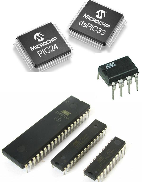
However, these microcontrollers need to be built on appropriate boards to be used and programmed and their programming is done with the connection on a computer.
Likewise, the board also predicts its connection to the circuits to be controlled and to the circuits that will provide the information for the control, such as sensors, keys, external keyboards, etc.
In practice, using the microcontroller this way is not very convenient because it requires a preparation of the board which in some cases can be problematic if the microcontrollers are of the types that are intended for surface mounting, with reduced sizes, as shown in Figure 3.
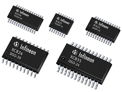
This type of microcontroller, with reduced housing, is intended for industrial applications where the applications in which they are to be used are built for machines.
A much simpler way of using the microcontroller, especially in experimental projects, for didactic purposes or isolated applications (which will not be industrialized) is through ready-made boards.
They are microcontrollers that are acquired built on small boards which already have all the resources for programming input through a simple cable and equipped with connectors to connect the circuits that must be controlled, sensors or control devices and of course the power supply.
These boards, in many cases, still have their own power circuit so that the external application can be done by a good voltage range as we will see.
In Figure 4 we have an example of a microcontroller board, one of the most popular, which is simple to use and works for a multitude of applications in mechatronics, robotics, automation, IoT, etc. We'll talk about this board later.
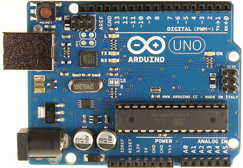
To better understand how the microcontroller and its board work, it will be interesting to analyze its internal structure given in Figure 5.
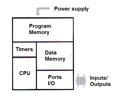
The most important block is the Central Processing Unit, well known as CPU, which consists of a processor capable of performing logic operations with digital signals.
We can say that it is the "brain" of the microcontroller, because it can make calculations and process information logically. The CPU does this through a program of its own.
Thus, as in the case of processors used in computers, microcontrollers understand only the language that is supplied to them from a digital way and can process information using only what they "know".
What they know is given by a set of instructions which they recognize knowing how to use when the information arrives.
So, if in our control program we say that the CPU must add the temperature read by one sensor with the temperature read by another, the values ??must be sent in digital form to the CPU and it must know what it is to add.
Microcontrollers have two memories.
The program memory is used to store the instructions or programs that tell what the microcontroller should do, for example, add the temperature of two sensors in a certain condition, if the temperature values ??coincide to turn on or off something, etc.
In a wearable which controls a sequence of LEDs producing an effect, it is in this memory that it is programmed.
The size of these memories varies according to the purpose and type of microcontroller. So when choosing a type for your applications should the designer be attentive to this feature.
These memories are EEPROM or Flash, that is, memories that retains information even when the microcontroller is turned off and can be reprogrammed when we connect it to a computer to program a new application.
In the data memory there is the information that the microcontroller will collect during its operation, for example, the readings of the sensors, to be used when necessary.
Another important block to be analyzed is the timers.
Many of the functions performed by microcontrollers require the use of precise time intervals. Turn on a key every once in a while, read a temperature or position sensor every 5 seconds. For this purpose there is a special programming block in which this can be done.
The processing of the microcontroller is very fast determined by the clock. This clock commands operations that can reach thousands or millions per second.
With the help of the timer, using the clock signal can achieve much slower control cycles.
The ports are in the next block of the basic structure consisting of the way the microcontroller has to communicate with the outside world, ie, in its interface with the outside world.
Input and output ports (I/O = Input/output) are accessed via pins of the microcontroller's integrated circuit and on the boards through connectors where we can make the connections of the external circuits, as shown in Figure 6.
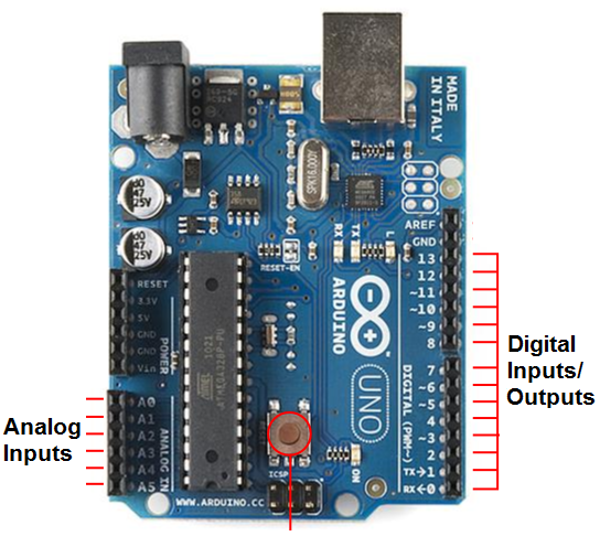
In many microcontrollers (to save pins) the same pins can be used for input and output. An internal command tells you the moment when they function as input and the moment they function as output.
In Figure 7 we have an example of a microcontroller in which the same pins can be used as input and output.

In the inputs we can connect several types of circuits, but they must have characteristics which allow the microcontroller to understand the signals that they provide.
Thus, we have digital inputs that are inputs in which digital signals compatible with the microcontroller must be applied, i.e., TTL or CMOS signals, in most cases 5 V. (There are also circuits that operate with 3.3 V signals)
We can connect to these inputs digital sensors that have the capabilities to digitize as they perform. In Figure 8 we have digital sensors.
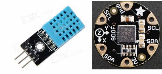
We can also connect simple sensors of type yes or no or On/Off like keys that send logic levels 0 and 1.
In the analog inputs we can connect sensors or circuits which provide signals that correspond to a certain range of voltages that the microcontroller must recognize.
Note that the processor circuit does not recognize analog values, so there is an internal analog-to-digital converter (ADC) circuit that turns analog information into digital.
Inside the microcontroller, everything that is passes in digital form.
When using analog inputs of a microcontroller the designer must know which is the range of voltages that can be applied in it, without danger of damage to the circuit.
As for the recognition of applied voltages, it only depends on the programming.
For exit doors, it is also important to know what kind of signs you can find in them.
The signals found are digital, i.e., the pulses or logical levels where the 0 or LO is given by a voltage of 0V and the 1 or HI is given by 5V. (Figure 9)
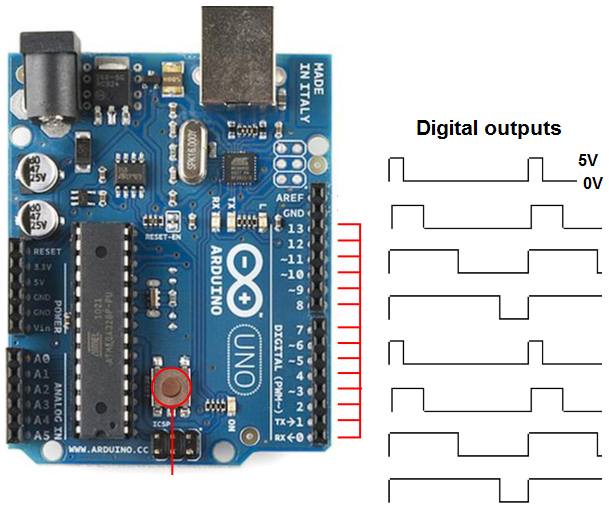
The current in these outputs is low, only allowing low-power devices like LEDs to be connected directly.
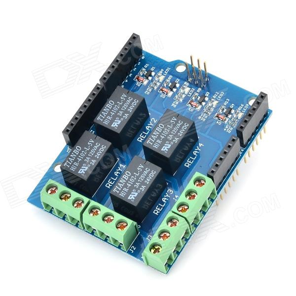
To use these signals in the control of higher consumption circuits, it is necessary to use intermediate circuits or drivers, called “shields” or boards with components which can be controlled directly, called breakout boards (Figure 10).
In Figure 11 we have an example of how to use a microcontroller to generate sequential effects on its outputs.
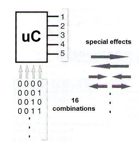
Simply connect the outputs to the shields which control the LEDs so they run producing the desired effects.
Very small bass microcontrollers are widely used in the sequences of LEDs used as Christmas ornaments.


