Development, learning and assessment boards
One very interesting feature that readers who wish to work with microcontrollers can count on is boards specifically designed to do specific jobs with microcontrollers.
The first group of boards is formed by starter kits consisting of assemblies sold by the major companies in which they have a microcontroller board already built, with the power supply and a set of components for certain applications, as shown in Figure 1.
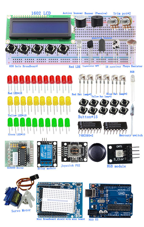
Included in this set is a book or learning booklet and the access to the program used with the cable for the connection to the computer.
They are ideal sets for those who want to learn how to use a particular type of microcontroller and make basic designs with them. In some cases, an array of contacts comes with the kit for connecting the circuit developed to the microcontroller.
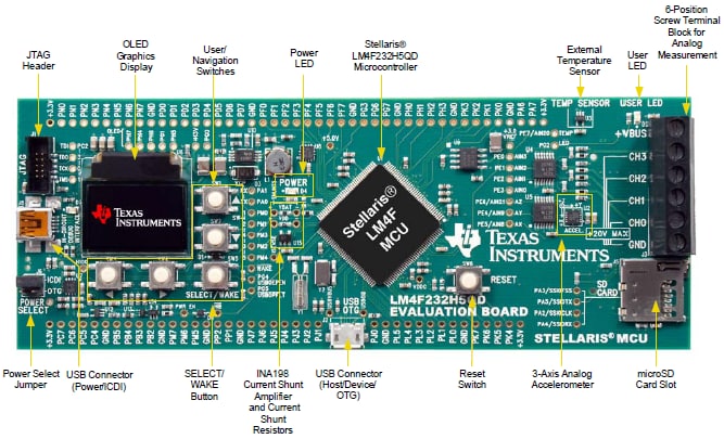
In a second group we have the so-called evaluation boards, which consist of boards which already have a programmed application and a test circuit that can eventually be modified.
This board enables the developer have an application ready for a microcontroller and eventually make program changes for the application that they want. In Figure 2 we have an example.
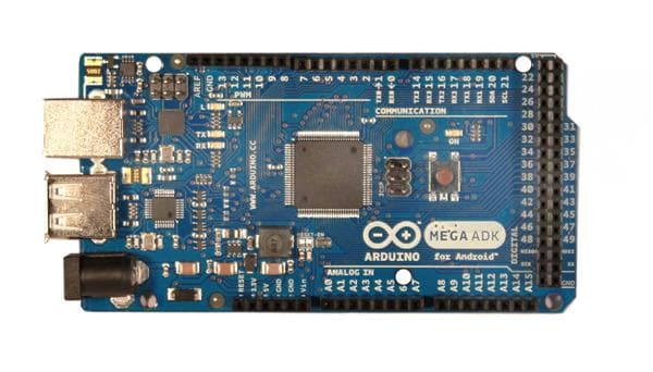
Finally we have the development boards which contain a microcontroller and specific regions for the development of projects of a certain category.
Usually these boards come with manuals and internet access for programming. Figure 3 shows a typical development board.
By consulting vendors such as Mouser (www.mouser.com) the reader can find a myriad of board types of all types for all available microcontroller families.
It will always be important to study the application first so that, through the desired characteristics, the specific board can be acquired.
The programming
The programming languages used in microcontrollers are the common ones like C, C ++, Pascal, Assembly, etc.
Normally, interpreters and compilers are used to work with programming.
The interpreters are "translators" that use a language close to the one we use, other than the 0 and 1 that the circuits understand, so we can write the orders that the microcontroller must execute. BASIC is an interpreter.
The compiler is a high-level translator which combines the ease of using common words with high-speed processing. A compiler program is already placed in the microcontroller's EPROM or downloaded to it.
An example of language that is used in microcontrollers for which there are easy-to-use compilers is C.
Of course, to work with the microcontrollers you must know how to program, that is, you must know the language that it uses and know how to use the compiler.
For this purpose there are many books and courses available and are quite simple.
In fact, this programming is the basis of the use of microcontrollers in school, where you learn the basic electronics, creating a circuit that triggers LEDs and writing the program that causes them to flash and also increasingly advanced circuits, such as controlling a robot or elevator.
In general, how microcontrollers process information is the same for everyone.
Thus, once one knows how to structure a program (the sequence of orders that the microcontroller must continue to generate the control signals) it is enough to "translate" them into the language it uses and it is done.
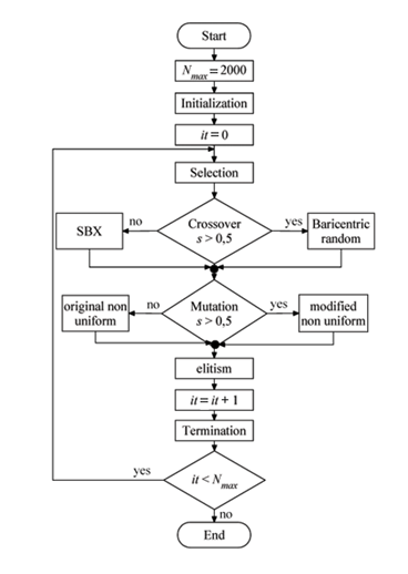
The structuring is done through a flowchart, as in Figure 4, in which everything the microcontroller must do is placed in a logical way for the program to be written.
Below is an example program for Arduino.
*/
// a função loop roda indefinidamente
void loop() {
digitalWrite(LED_BUILTIN, HIGH); // turn the LED on (HIGH is the voltage level)
delay(1000); // wait for a second
digitalWrite(LED_BUILTIN, LOW); // turn the LED off by making the voltage LOW
delay(1000); // wait for a second
}
But, you do not have to program everything when doing a project, especially if it is simple.
Sketches are available on the internet that are nothing more than parts or small programs ready to be used.
Someone has taken the trouble to write these programs and use them and they can be added to your project without problems.
The program given above to flash an LED is an example of a sketch. If in your application there will be one or more blinking LEDs, you already have the program excerpt that makes it.
The circuit to use this program flashing an LED is in Figure 5.
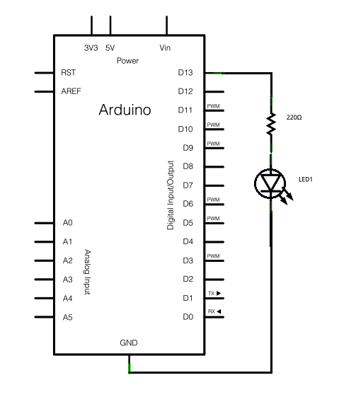
We can use the same program to intermittently drive a motor by connecting a control shield to the D13 output. We also change the delay lines for the periods we want.
Using other outputs we can blink in different ways other LEDs or produce decorative or wearable effects, for example.
Where they are used
Applications for microcontrollers are unlimited. Where we need the control of one or more devices from a programming that involves automation or even the control from external signals we can use a microcontroller. This is not limited to robotics and mechatronics (automation and control) but to other branches that are currently expanding like IoT and wearable.
Some examples of application:
- Autonomous robots
- Robotic arms
- Drones
- Alarms
- Elevators
- Automatic gates and access control
- Home appliances
- Sensor monitoring
- Industrial controls
- General automation
- Intelligent personal clothing and household articles
The main families
Our space is insufficient to address in detail all the families of microcontrollers available, even though every day new types with new features are released.
We suggest to consult the Internet, mainly Mouser’s website which has in its stocks practically all microcontrollers available with access to datasheets, which greatly facilitates the choice of a specific type for its application.
Let's then give some basic information about the main types.
Arduino
This is undoubtedly the main family of microcontrollers, mainly for didactic use, given their ease of use, low cost and performance.
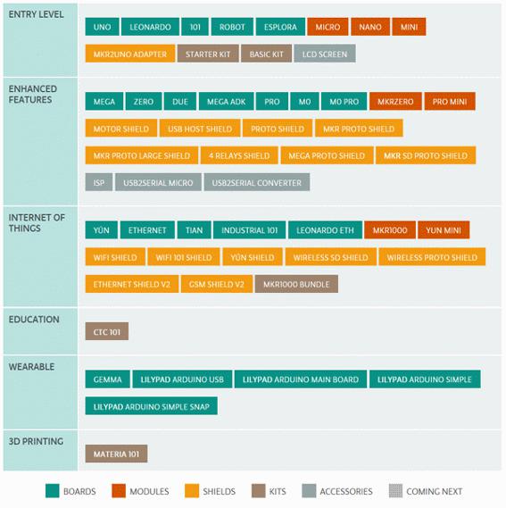
Created in Italy, today the Arduino has several types such as Uno, Nano, Leonardo, Micro, Mega, Zero, with a multitude of variations, as shown in the table below
https://www.arduino.cc/en/Main/Products.
The Arduino boards are based on Atmel’s Atmega microcontrollers which can be used in applications similar to those created in Arduino, but independently. (Figure 6)
For educational robotics, initiation, STEM, the UNO board is the most recommended. (figure 7)
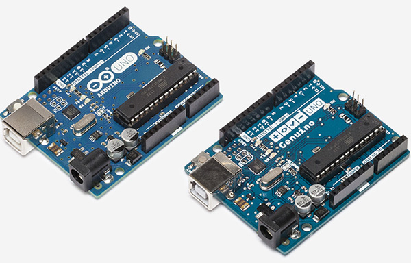
The basic characteristics of this microcontroller (version Uno) are:
of which 0.5 kB used by bootloader
| Microcontroller | ATmega328P |
| Operating Voltage | 5V |
| Input Voltage (recommended) | 7-12V |
| Input Voltage (limit) | 6-20V |
| Digital I/O Pins | 14 (of which 6 provide PWM output) |
| PWM Digital I/O Pins | 6 |
| Analog Input Pins | 6 |
| DC Current per I/O Pin | 20 mA |
| DC Current for 3.3V Pin | 50 mA |
| Flash Memory | 32 kB (ATmega328P) |
| SRAM | 2 kB (ATmega328P) |
| EEPROM | 1 kB (ATmega328P) |
| Clock Speed | 16 MHz |
| LED_BUILTIN | 13 |
| Length | 68.6 mm |
| Width | 53.4 mm |
| Weight | 25 g |
Intel Galileo and Edison
Intel has in its simplest line of microcontrollers for use in robotics, mechatronics, IoT and for educational purposes, two types that at the time of the production of this book were quite important.
Both types are available in the form of a development platform containing Intel processors and compatible with various expansion features. In addition, both platforms can run on Linux
Intel Galileo
The Galileo development board can be compared to a more advanced version of the Arduino, because it is compatible with it and with more resources, allowing more complex projects to be carried out. (figure 8)
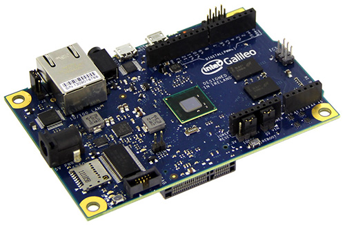
Its main specifications are as follows:
- uses an Intel® Quark SoC x 1000 processor
- has 256 MB of RAM
- has 8 NB of flash memory
- has multiple interfacing features in the industry standard
- Mini-PCI Express Slot
- 100 Mb Ethernet Port
- Micro SD slot for support of 32 GB of additional memory
- USB host port
- USB customer port
- Arduino Compatibility
- Supports Linux Yocto 1.4 Pocky
- Supports multiple development platforms
Galileo behaves like a mini-PC given the amount of connectivity options such as access to the Internet, 3G module, Wi-Fi, Ethernet port, etc.
Intel Edison
Unlike Intel Galileo, Intel Edison is a board specifically designed for the development of low-cost projects. (figure 9)
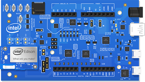
- SoC 22 nm Intel® Atom
- 1GB of RAM
- 4 GB flash memory
- Wi-Fi
- Blue Tooth Low- Energy (LE)
- Less than 1 W of consumption at full operation
- USB ports
- 40 GPIO interfaces ideal for connecting sensors, LCD screen and several expansion cards.
More information about Intel on https://software.intel.com/en-us/articles/spotlight-on-intel-galileo-and-intel-edison-development-boards


