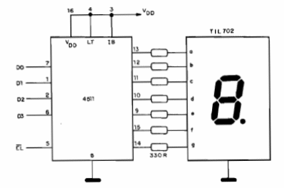
7 Segment Decoder Shield
Although 7 Arduino outputs can be used to excite a 7-segment display, or even more displays with multiplexing, this solution requires only 4 outputs or 5 outputs with clear because the data is digitally encoded. The circuit below shows how to use the 4511, a 7-segment CMOS decoder for a common cathode display. The resistors can be 330 ohms or 470 ohms and the supply voltage of the circuit will be 5 V for the common microcontrollers. The inputs must be made by TTL logic levels and the clear CL input or it zeroes the display.
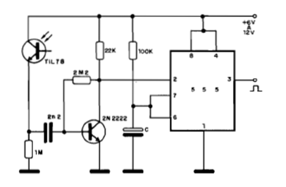
Infrared Monostable Shield
Upon receiving a pulse of infrared radiation of sufficient intensity, this circuit triggers producing at its output a single pulse duration which depends on C. C can have values between 1 nF and 1 000 uF. With the higher values, and also increasing the resistor of 100k, we can get pulses of tens of minutes in duration. The circuit can be powered by voltages of 5 to 12 V and optical features should be used to increase sensitivity and avoid interference from other light sources. As a shield, it can be used in a simple control or infrared detector.
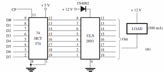
Multiple Power Interface Shield
With this circuit it is possible to control several loads up to 500 mA from the outputs of an Arduino, microcontroller or even a parallel port of a PC. The loads are activated with the outputs on the low level. The sources should be separate, but they should all have a common ground with the controller. The circuit is in the book Mechatronics Sourcebook by Newton C. Braga, published in the United States.
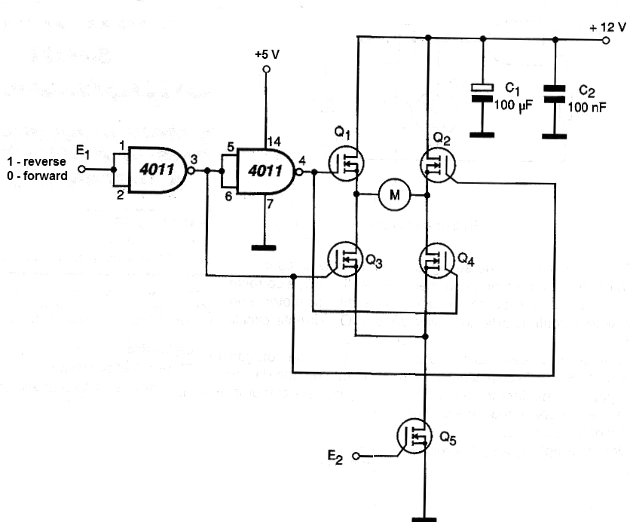
Motor Control Shield with an External PWM
This circuit is a variation of the previous one, counting on a PWM control input which must have signals of at least 5 V. If there is difficulty of driving with the microcontroller used and the chosen MOSFET, an additional step fed by 12 V with a bipolar transistor should be used, for example. This is also true for the CI output of the rotation direction control.
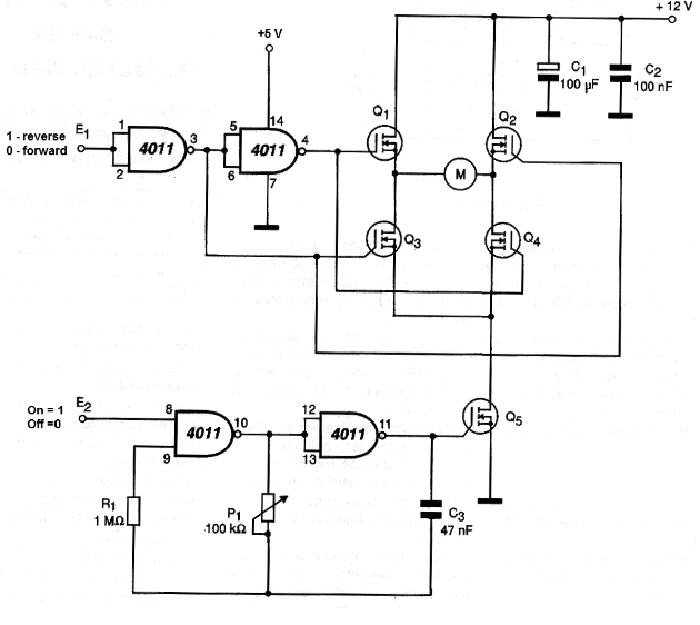
Shield Using an H-Bridge with a Manual PWM Control
This Shield for a motor control with an H-bridge has an additional trigger circuit for a PWM control. This control is manual in principle, made by a potentiometer, but there can be used a resistive sensor which will then determine the speed of the motor. In a robot which follows the light, for example, using as a sensor an LDR, we can obtain the acceleration when the light source is located. The circuit should operate with 5 V, because with lower voltages for the IC the MOSFET trigger can be problematic. Any power MOSFET can be used.
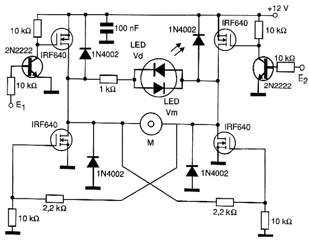
Complete H-Bridge Shield with MOSFETs and a Direction Indicator
This complete bridge has two additional LEDs which indicate the direction of rotation of the controlled motor. The bridge makes use of power MOSFETs and types must be chosen according to the current of the controlled motor. These transistors must be fitted with heat triggers. The bridge can be controlled by both, 3 and 5 V signals, and situation 11 is forbidden.
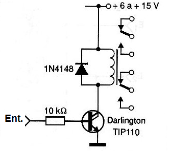
Shield For Relay Drive at the Motor Control 1
What differentiates this circuit from the previous one is the need for a much smaller current for the triggering. The relay can be 6 or 12 V depending on the power supply and the source for both, the motor and this circuit, must be separated from the microcontroller. This avoids the interference problem of the motor brushes.
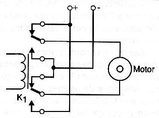
Shield for Motor Reversion With a Relay
In order to invert the rotation of an engine by changing the levels of an output of an Arduino or other microcontroller, we can use a relay of 5 V as shown below. The motor has independent power supply. To switch the motor on and off, a second relay can be used. For higher voltage relays it is convenient to use a driving stage as given in the next circuit.
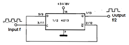
Frequency Divider (by 2) Shield
The frequency of the input signal, up to a few megahertz, is divided by 2 in this circuit which uses half of the double 4013 flip-flop. We can associate several of these circuits to make the successive division. The input signal must be compatible with the CMOS logic and free from bounces. In the schematic numbering, we have the pins for the two 4013 flip-flops. The circuit can be used in an input Shield which provides a signal whose frequency needs division.
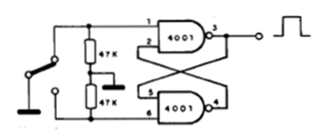
Anti-Bounce Switch
This Input Shield is important because it prevents signals from a sensor or a key from being misinterpreted by a microcontroller due to the presence of bounces. The closing of the switch causes several accommodating pulses which are counted by the microcontroller. In the figure, we have an anti-bouce circuit using a 1-pole x 2-way switch. The integrated circuit is 4001 and the positive power is made at pin 14. The negative is done at pin 7. The power of 4081 must be made with 3 or 5 V according to the microcontroller.
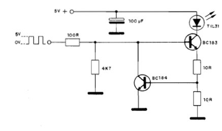
High Power Modulator Shield
This circuit is suitable for high current LEDs (up to 200 mA) operating with TTL signals on an infrared data link or PWM remote control, for example. The transistor can be replaced by the equivalent of 2N2222 or 2N2218. The receiver for this transmitter is the previous circuit. The circuit is suggested by Texas Instruments in its Optoelectronics Manual.
Infrared Receiver Shield for a Microcontroller
The purpose of this circuit is to receive and amplify the modulated infrared radiation received by the photo sensor. The circuit must be powered by voltages from 5 to 12 V and its consumption is very low. For the case of compatibility with Arduino and other microcontrollers powered by 5 V, this should be the voltage used. The circuit is high speed, and can operate with some megahertz. The photo sensor must be equipped with optical features for greater sensitivity and directivity, thus increasing the range.
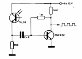
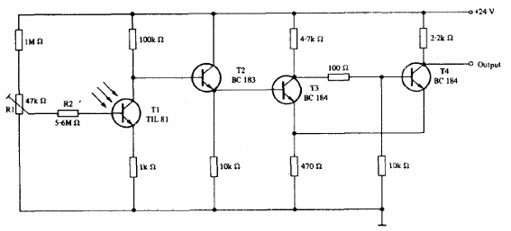
Photo Trigger Shield of Low Current
The current of the Schmitt optical trigger is very low in the dark. The transistors can be BC548 and the adjustment of the current in the dark is made at the trimpot. Observe the output voltage of this circuit. A resistive divider must be added to obtain the driving voltage of the inputs of an Arduino or another microcontroller. The circuit is from an optoelectronic manual from Texas Instruments.
