RedFox Kit
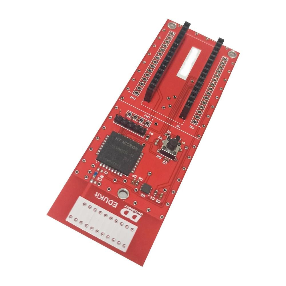
This project adopts the RedFox development kit, authored by Luiz Henrique Corrêa Bernardes. The development kit, sold along with the book "IoT SigFox com Edukit Redfox" (written by the same author), supports the use of the IoT SigFox network using an Arduino Nano for programming and an HT32SX microcontroller, from Brazilian manufacturer HT Micron, for SigFox "modem". As such, this is one of the few excellent development kits made primarily from Brazilian components. Plus, the kit comes with one year of SigFox connectivity free of charge, allowing you to evaluate SigFox services.
The development kit requires using an Arduino Nano for the user to program the project/solution. This makes using the kit straightforward, as it is possible to program it identically to an ordinary Arduino.
The development kit and book can be purchased at the Curto-Circuito virtual store, at the following address: https://www.curtocircuito.com.br/kit-iot-sigfox-com-edukit-redfox.html .
Required Components
To build this project, you will need the following components:
• RedFox development kit
• Arduino Nano V3
• DHT11 sensor
• MQ-2 sensor
• 10k 1/4W resistor
• 1x40 female pin bar
• Male-male and male-female jumpers
• 400-contacts prototype board
Overview - Project
The project in this article consists of:
• Measure, every second, the room temperature and monitor the presence of flammable gases and smoke in the air;
• With the measurement results, in case of detection of the presence of flammable gases or smoke in the air, send an immediate message via SigFox alerting the circumstances;
• In common cases (without detection of flammable gases or smoke in the air), the room temperature and status of the flammable gas and smoke sensor is sent every 30 minutes via SigFox.
Such information, when received on the SigFox backend, will be automatically forwarded to the TagoIO platform.
The entire project is available, open-source and open-hardware, at https://github.com/phfbertoleti/monitoramento_gases_inflamaveis_sigfox .
Circuit Schematic
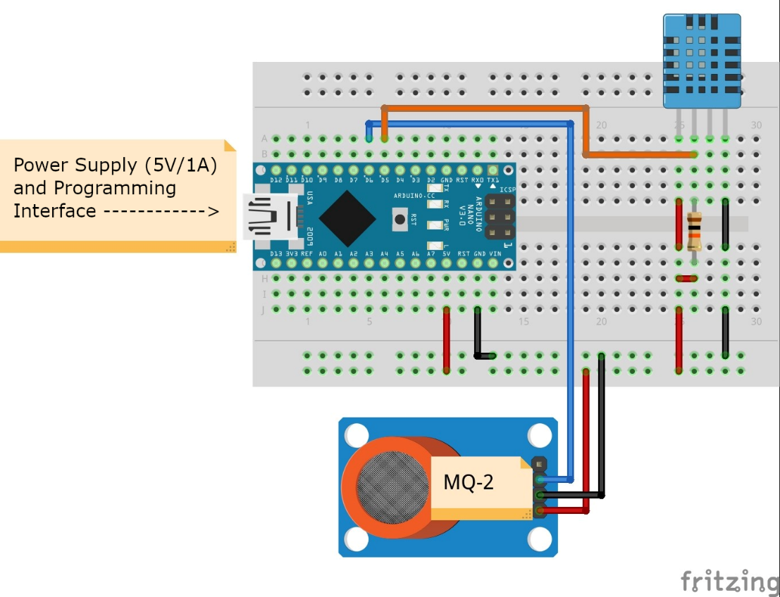
The solution's circuit schematic can be seen in Figure 2.
It is important to note that it refers to the Arduino Nano connections that are socketed on the RedFox kit. Therefore, it is necessary to solder the female pin bar to the RedFox board (on the mirrored terminals of the Arduino Nano).
DHT11 Sensor - Overview
The DHT11 is a sensor capable of measuring room temperature and relative humidity. It has only four terminals, and it is easy to connect to microcontrollers, making it a very popular sensor option for room temperature and relative humidity. Such a sensor can be seen in Figure 3.
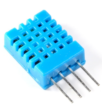
The DHT11 has the following specifications:
• Relative air humidity measurement range: from 20% to 90%
• Temperature measurement range: from 0ºC to 50ºC
• Supply voltage range: 3V up to 5.5V
• Error in the measurement of relative air humidity: ± 5.0%
• Error in room temperature measurement: ± 2.0 ºC
MQ-2 Sensor - Overview
The MQ-2 is a sensor capable of detecting the presence of smoke and the following gases in the air:
• LPG
• Methane
• Propane
• Butane
• Hydrogen
• Alcohol
• Natural Gas
The module commonly sold with this sensor can be seen in Figure 4.
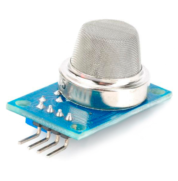
It has only four terminals and is easy to connect to microcontrollers, making it a very popular sensor option for detecting flammable gases or smoke in the air. The specifications of this module with an MQ-2 sensor can be seen below:
• Detection concentration: from 300 ppm to 10,000 ppm
• Operating voltage: 5V
• Adjustable sensitivity via potentiometer
• Digital and Analogue Output
TagoIO IoT Platform
This project employs the IoT TagoIO platform to display the data received via SigFox. Below, you will find the complete procedures for integrating with the platform, from account creation to dashboard creation.
TagoIO Account Creation
To create your free account on the IoT TagoIO platform ( https://tago.io ), please follow the procedure below:
1. Register your account by filling in the required data on the registration page: https://admin.tago.io/signup. You must provide an available and valid email (to which you have full access). Once the data has been filled in, click on Register.
2. You will be redirected to a screen asking if you are a new user or already know TagoIO. As the step-by-step instructions for using the IoT platform will be provided in this article, you can click on the option to inform you already know TagoIO (I already know TagoIO option, as shown in Figure 1). However, if you want to take the initial tour of the IoT platform and get to know it a little more, feel free to click on the option I'm new at TagoIO, as shown in Figure 5.

3. You will receive an email from TagoIO requesting your account creation confirmation. Confirm the account as instructed in the email and log back into your TagoIO account (with registered email and password) at https://tago.io.
4. From that point on, your TagoIO account is created and ready to use.
Integration Of SigFox Backend With TagoIO
To integrate the SigFox backend, follow the entire procedure indicated on the website https://docs.tago.io/en/articles/172-sigfox-downlink .This procedure will cause all raw data received via SigFox from your device to be automatically and securely forwarded to the IoT TagoIO platform. Therefore, such data can be displayed in dashboards and worked/processed as you wish in the future.
Creation Of The Parser On The TagoIO Platform
Once the integration between SigFox and TagoIO backend is completed, it is needed to program a routine to distribute the raw data received into variables. That is, inform the TagoIO platform how to separate the useful data for later displaying and processing. This routine for distributing incoming raw data into variables is called a parser. To create the parser of this project, please follow the procedure below:
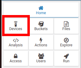
1. On the TagoIO platform, click on Devices, as shown in Figure 6.
2. Once in the device management screen, click on the name of your SigFox device.
3. On the information screen of your SigFox device, click on the Payload Parser tab.
4. Enable the Run your own parser option, as shown in Figure 7.

5. There will be a large text field for entering your own code for the parser. In this space, enter the code below and then click Save.
const payload_raw = payload.find(x => x.variable === 'data');
if (payload_raw) {
try {
const buffer = Buffer.from(payload_raw.value, 'hex');
/* Extract variables from payload received by SigFox */
const temperature = buffer.readUInt8(0);
const status_sensor_flammable_gases = buffer.readUInt8(1);
var text_sensor_flammable_gases = "";
if (status_sensor_flammable_gases == 1)
text_sensor_flammable_gases = "Flammable gas or smoke detected!";
else
text_sensor_flammable_gases = "Ok";
const data = [{
variable: 'temperature',
value: temperature,
unit: '°C'
},
{
variable: 'text_sensor_flammable_gases',
value: text_sensor_flammable_gases,
unit: ' '
},
];
payload = payload.concat(data.map(x => ({
...x,
serie: payload_raw.serie,
time: payload_raw.time
})));
} catch (e) {
console.error(e);
payload = [{
variable: 'parse_error',
value: e.message
}];
}
}
6. Done! All raw data received via SigFox and automatically forwarded to the TagoIO platform will be automatically distributed into variables by the parser.
Creating A Dashboard
From this point onwards, all data received from your SigFox device is already accessible in the form of variables, which refer to room temperature and detection status of flammable gases or smoke. Now, we're going to display such data in a dashboard, allowing you to track incoming data in an aesthetically pleasing way visually. To do this, follow the procedure below:
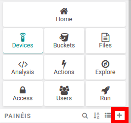
1. To start creating a new dashboard, click on the + option in the PANELS section, as shown in Figure 8.
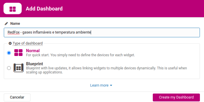
2. You will be prompted for the name of the dashboard to be created. Enter RedFox - Flammable Gases and Room Temperature in the Name field and click on Create my Dashboard, as shown in Figure 9.
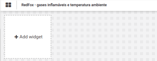
3. Your dashboard (still empty) is created. Now is the time to add items to the dashboard so that each item displays a specific variable. This item is called a widget. To create a widget, click on the "Add widget" button (or the + button in the upper right corner of the dashboard), as shown in Figure 10.
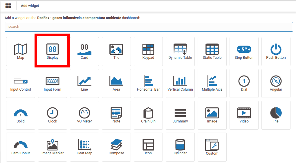
4. Select the Display type widget, as highlighted in Figure 11.
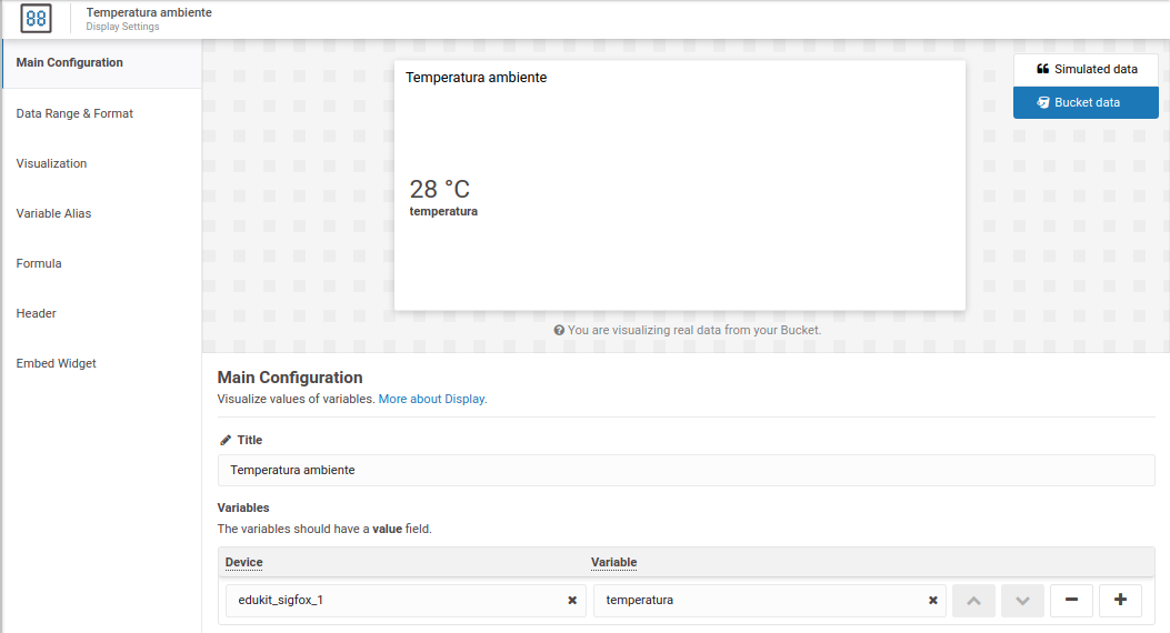
5. In the Display widget configuration screen, fill in as shown in Figure 12, replacing the device name with your device name (the name when it was created). After filling in the data, click on Save.
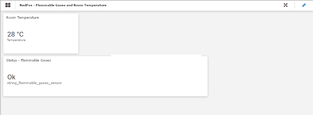
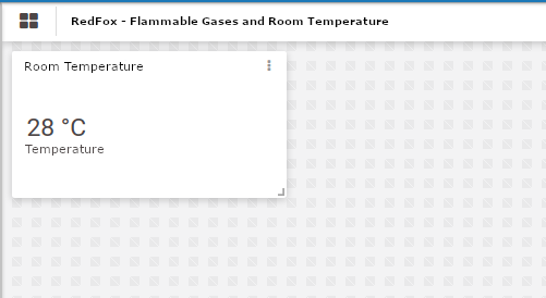
6. At this point, the first widget of your dashboard (which shows the room temperature) has been created, as shown in Figure 13. In your case, the warning that no data is available may be shown in the newly created widget. This happens because there is still no device data on the TagoIO platform. That way, as soon as data is received, it will automatically populate this and the other widgets included in your dashboard.
7. Repeat the procedure from steps 3, 4, 5 and 6, replacing the variable name for text_sensor_flammable_gases and replacing the widget title for Status - Flammable Gases. This is the widget that will show the flammable gases or smoke detection status on your dashboard.
8. Ao fim do procedimento, o seu dashboard estará conforme mostra a figura 14.
9. Click the eye-shaped button in the upper-right corner of your dashboard. Your dashboard will be placed into view mode.
10. From now on, for each data transmission from your SigFox device, the data will be displayed in the dashboard.
Project Source Code
The project's source code can be seen below.
/* Program: Room Temperature And Flammable Gases Monitoring with SigFox
* Autor: Pedro Bertoleti
*/
#include <SoftwareSerial.h>
#include "DHT.h"
/* Settings - sensors */
#define DHTPIN 5
#define DHTTYPE DHT11
#define GPIO_MQ2 6
#define FLAMMABLE_GAS_NOT_DETECTED 0x00
#define FLAMMABLE_GAS_DETECTED 0x01
#define WRITE_DEBUG_SENSORS
/* Settings - breathing light */
#define TIME_BREATHING_LIGHT 500 //ms
/* Settings - MQ-2 burn-in time */
#define TIME_BURNIN_MQ2 180 //s (3 minutos)
/* Settings - AT commands for HT32SX */
#define CMD_AT_HT32SX_RESET "AT+RESET;"
#define CMD_AT_HT32SX_RCZ2 "AT+CFGRCZ=2;"
#define CMD_AT_HT32SX_SEND_BYTES "AT+SEND=0:" //no downlink
#define CMD_AT_HT32SX_ENTER_DEEP_SLEEP "AT+DEEPSLEEP;"
#define CMD_AT_HT32SX_EXIT_DEEP_SLEEP "AT+WKP;"
/* Settings - time between SigFox uploads */
#define TIME_BETWEEN_PUSH_SIGFOX 1800000 /* 1800000ms = 30 minutes */
/* Settings - GPIOs used to communicate with HT32SX */
#define RESET 4 /* Reset HT32SX */
#define TX 2 /* Serial TX (Nano -> HT32SX) */
#define RX 3 /* Serial RX (Nano <- HT32SX) */
/* Settings - LED GPIO */
#define LED 13
/* Settings - serial communications baudrates */
#define BAUDRATE_SERIAL_DEBUG 115200
#define BAUDRATE_SERIAL_HT32SX 9600
/* Serial software control object
(for Nano communication <-> HT32SX) */
SoftwareSerial serial_HT32SX(RX, TX);
/* DHT11 reading object */
DHT dht(DHTPIN, DHTTYPE);
/* Global variables */
unsigned long timestamp_meas_temp_gas;
unsigned long timestamp_send_sigfox;
unsigned long timestamp_breathing_light;
int temperature = 0;
char sensor_gas = FLAMMABLE_GAS_NOT_DETECTED;
bool led_on = false;
char at_command_send_sigfox[20] = {
0
};
bool flammable_gases_alarm_sent = false;
/* Prototypes */
void hardware_reset_HT32SX(void);
void send_command_AT_HT32SX(char * pt_command);
unsigned long time_difference(unsigned long tref);
void wait_and_show_reception_HT32SX(void);
void send_message_sigfox(void);
/* Function: resets (via hardware) the HT32SX
* Parameters: none
* Return: none
*/
void hardware_reset_HT32SX(void) {
digitalWrite(RESET, HIGH);
delay(1000);
digitalWrite(RESET, LOW);
delay(100);
}
/* Function: send AT command to HT32SX
* Parameters: pointer to command string
* Return: none
*/
void send_command_AT_HT32SX(char * pt_command) {
char cmd_buffer[50] = {
0
};
memcpy(cmd_buffer, pt_command, strlen(pt_command));
serial_HT32SX.write(cmd_buffer, strlen(cmd_buffer));
serial_HT32SX.flush();
}
/* Function: calculates the difference between
* current time and a time reference
* Parameters: time reference
* Return: calculated time difference
*/
unsigned long time_difference(unsigned long tref) {
return (millis() - tref);
}
/* Function: wait for data reception
* from HT32SX by UART
* Parameters: none
* Return: none
*/
void wait_and_show_reception_HT32SX(void) {
unsigned long timestamp_reception_serial;
char c;
timestamp_reception_serial = millis();
while (time_difference(timestamp_reception_serial) <= 3000) {
if (serial_HT32SX.available()) {
c = serial_HT32SX.read();
Serial.print(c);
}
}
}
/* Function: send message via SigFox
* Parameters: none
* Return: none
*/
void send_message_sigfox(void) {
/* Wake up HT32SX, configure the communication zone
and send SigFox message */
send_command_AT_HT32SX(CMD_AT_HT32SX_EXIT_DEEP_SLEEP);
wait_and_show_reception_HT32SX();
hardware_reset_HT32SX();
wait_and_show_reception_HT32SX();
send_command_AT_HT32SX(CMD_AT_HT32SX_RCZ2);
wait_and_show_reception_HT32SX();
/* Formats and sends AT command */
memset(at_command_send_sigfox, 0x00, sizeof(at_command_send_sigfox));
sprintf(at_command_send_sigfox, "%s%02x%02x;", CMD_AT_HT32SX_SEND_BYTES,
(unsigned char) temperature,
(unsigned char) sensor_gas);
#ifdef WRITE_DEBUG_SENSORS
Serial.print("AT command: ");
Serial.println(at_command_send_sigfox);
#endif
send_command_AT_HT32SX(at_command_send_sigfox);
wait_and_show_reception_HT32SX();
/* HT32SX goes into sleep mode again */
send_command_AT_HT32SX(CMD_AT_HT32SX_ENTER_DEEP_SLEEP);
wait_and_show_reception_HT32SX();
}
void setup() {
int count_seconds_burnin_mq2;
/* Initializes serial communications */
Serial.begin(BAUDRATE_SERIAL_DEBUG);
serial_HT32SX.begin(BAUDRATE_SERIAL_HT32SX);
Serial.println("SigFox - temperature and humidity monitor");
Serial.println("Wait 3 minutes for MQ-2 sensor burn-in time...");
/* Initialize GPIOs */
pinMode(RESET, OUTPUT);
digitalWrite(RESET, HIGH);
pinMode(LED, OUTPUT);
digitalWrite(LED, LOW);
pinMode(GPIO_MQ2, INPUT);
/* Initialize DHT11 */
dht.begin();
/* Reset HT32SX via hardware, via software and configure zone to RCZ2 */
hardware_reset_HT32SX();
delay(8000);
send_command_AT_HT32SX(CMD_AT_HT32SX_ENTER_DEEP_SLEEP);
count_seconds_burning_mq2 = 0;
while (count_seconds_burning_mq2) {
Serial.print("Remaining time: ");
Serial.print(TIME_BURNIN_MQ2 - count_seconds_burning_mq2);
Serial.println("s");
count_seconds_burning_mq2++;
delay(1000);
}
/* Initialize measurement timing of:
* - Temperature and humidity
* - Sending SigFox
* - Breathing light
*/
timestamp_meas_temp_gas = millis();
timestamp_send_sigfox = millis();
timestamp_breathing_light = millis();
}
void loop() {
char c;
/* Write messages received from UART with HT32SX */
if (serial_HT32SX.available()) {
c = serial_HT32SX.read();
Serial.print(c);
}
/* Blinks breathing light */
if (time_difference(timestamp_breathing_light) >= TIME_BREATHING_LIGHT) {
if (led_on == false) {
digitalWrite(LED, HIGH);
led_on = true;
} else {
digitalWrite(LED, LOW);
led_on = false;
}
timestamp_breathing_light = millis();
}
/* Measures the temperature and le sensor gas per second */
if (time_difference(timestamp_meas_temp_gas) >= 1000) {
/* Read current temperature */
do {
temperature = (int) dht.readTemperature();
} while ((isnan(temperature)) || (temperature <= 0));
/* Le MQ-2 gas sensor.
If flammable gas is detected,
force sending of a message. */
if (digitalRead(GPIO_MQ2) == HIGH) {
sensor_gas = FLAMMABLE_GAS_DETECTED;
if (aflammable_gases_alarm_sent == false) {
send_message_sigfox();
alarmflammable_gases_alarm_sentue;
timestamp_send_sigfox = millis();
}
} else {
sensor_gas = FLAMMABLE_GAS_NOT_DETECTED;
alarmflammable_gases_alarm_sentlse;
}
#ifdef WRITE_DEBUG_SENSORS
Serial.print("Room temperature: ");
Serial.print(temperature);
Serial.println("C");
if (sensor_gas == FLAMMABLE_GAS_DETECTED) {
Serial.println("Flammable gas: detected!");
} else
Serial.println("Flammable gas: not detected");
Serial.println("------");
#endif
timestamp_meas_temp_gas = millis();
}
/* Check if it is time to send measurements via SigFox */
if (time_difference(timestamp_send_sigfox) >= TIME_BETWEEN_PUSH_SIGFOX) {
send_message_sigfox();
timestamp_send_sigfox = millis();
}
}
Conclusion
In this article, you learned how to build an electronic device capable of monitor room temperature and the presence of flammable gases or smoke in the air, using SigFox as wireless communication technology. Also, you learned how to use the TagoIO IoT platform integrated with the SigFox backend, allowing the data received from the electronic device to be automatically forwarded to TagoIO for future processing and displaying. Also, you learned how to handle the received data (parser) and display the processed data (variables) in a dashboard. You can build on this project and create your own electronic devices for monitoring many variables, paving the way for many exciting projects that are very useful in real situations. As further advice, you can learn more about the TagoIO platform and design your IoT projects more professionally and robust with SigFox.

