
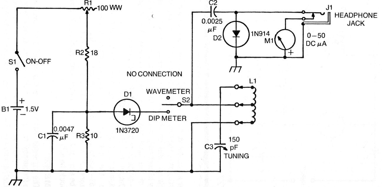
This circuit is from a 1976 technical documentation, and there may be difficulties in obtaining the original components, mainly the tunnel diode. For L1 we have a socket in which coils for the different frequency bands under test are connected. The indicator is a 50 uA instrument, but the lowest current range can be used. Power is provided by a single battery and the adjustment potentiometer R1 must be made of wire. The circuit operates at frequencies up to more than 1 GHz, depending only on the coil used. With switch S2 off, the circuit works as a field strength meter.
| Clique na imagem para ampliar |


