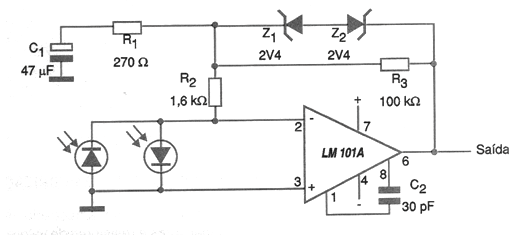
National Semiconductor suggests the circuit shown in the figure for amplifying signals from two photodiodes. The circuit is logarithmic, that is, it has its greatest gain with the small intensities of light falling on the diodes and as the intensity increases, the gain decreases when the two opposite zener diodes conduct, leading the circuit to unitary gain. The power supply must be symmetrical, and the largest gain is determined by R3. This component can be increased to obtain greater gain with lower light intensities. An interesting possibility is to replace R3 with a trimpot to obtain an adjustment of the dynamic operating range of the circuit. R1 also influences the circuit gain. The C2 capacitor does the frequency compensation and the photodiodes depend on the application, remembering that these components have a good frequency response for the modulated signals. Other operational amplifiers of the same characteristics can be tried out in this configuration.