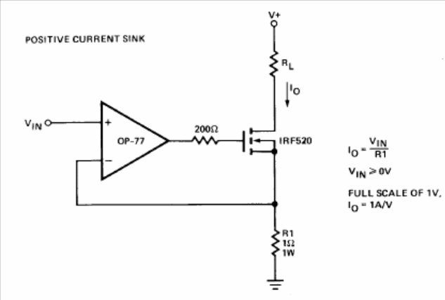
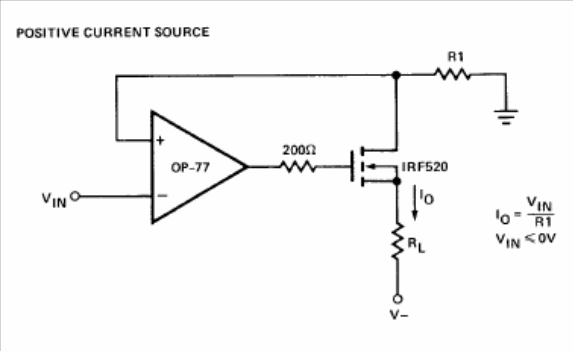
In figures 1 and 2 we have two current drains that can be made with operational amplifiers and power field effect transistors. The circuit in figure 1 is a current drain with the operating characteristics shown in the diagram itself. On the other hand, the circuit of figure 2 consists of a current source with the characteristics also given in the diagram. For both circuits, the power field effect transistors must be mounted on appropriate heat sinks. The power supplies for the two circuits must be symmetrical and equivalents can be tried, as long as they have the same characteristics.


