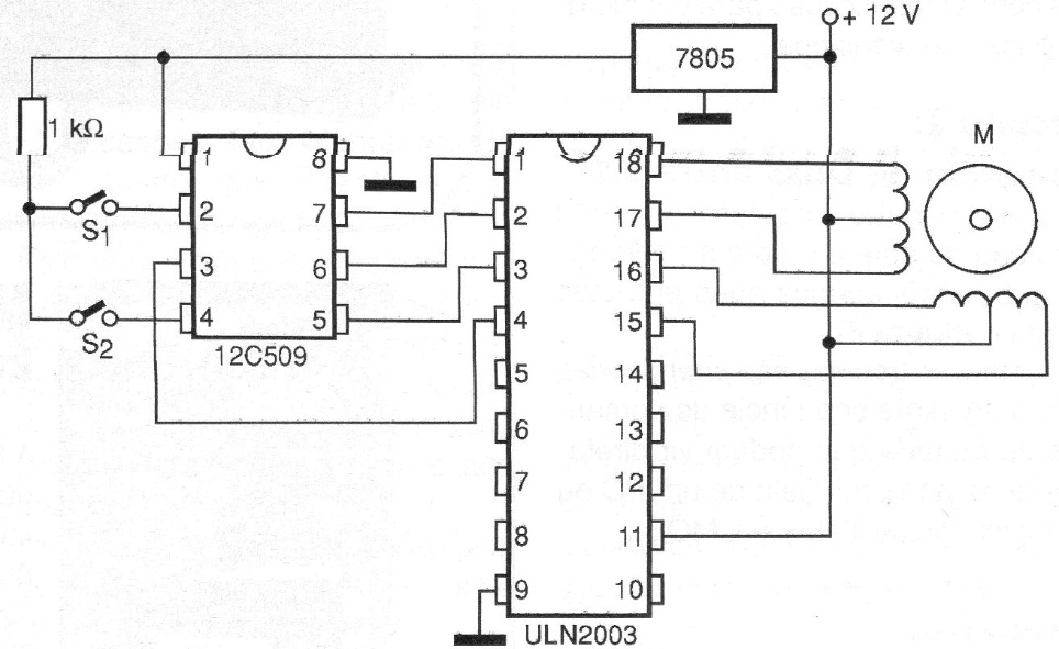
In this application we use an additional input circuit to enable the logic command with keys, sensors, or other resources. With adaptations the control signal can come from the outputs of a microcontroller. In this case, we can use it as a shield. The activation of each motor coil will depend on the combination of levels provided by the input sensors according to a table like the previous circuit (CIR7834). The integrated circuit used is the ULN2803 which can also control motors up to 500 mA per winding. Note that we have a 5 V voltage regulator circuit that reduces the 12 V of the motor source to 5 V necessary to supply the 12C509 logic circuit. Unused inputs to this circuit must be grounded through a 10k ohm resistor to prevent operating instabilities. The 7805 integrated circuit will not need a heat radiator due to the low current it must supply.