
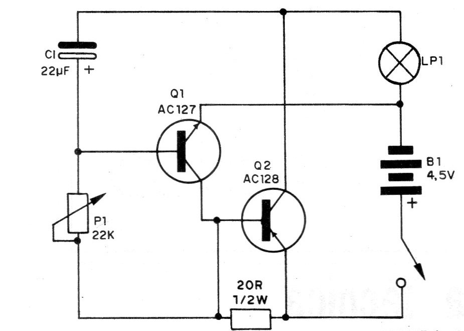
This project was found in a 1981 documentation consisting of a simple blinker with 2 transistors. The complete circuit of the flasher is shown in the figure. Two complementary transistors are used and as a load a lamp of up to 100 mA with an operating voltage between 2.5 and 4.5 V. To control larger loads the reader suggests connecting a relay as a load. The circuit frequency is basically determined by capacitor C1 and potentiometer P1. With the values shown in the diagram, frequencies around 1Hz can be used, but if the reader wants to, he can change the times achieved by changing the capacitor for another one of a different value. Higher value will give you more time between blinks, ie less frequency.
| Clique na imagem para ampliar |


