
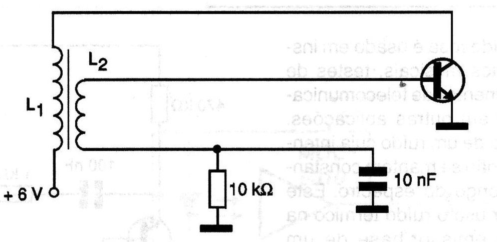
The oscillator shown in the figure can generate signals from a few tens of kilohertz up to approximately 10 MHz depending on the coils L1 and L1. In practical applications L2 has 1/5 of the turns of L1. To generate signals around 1 MHz, L1 has 100 turns of wire 22 on a 1 cm diameter ferrite rod and L2 consists of 20 turns of the same wire on the same rod over L1. A variable capacitor can be connected in parallel with L1 to adjust the frequency. If the circuit does not oscillate, invert one of the coils.
| Clique na imagem para ampliar |


