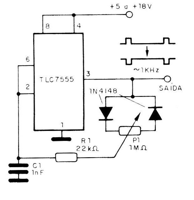
To obtain a signal with a variable mark / space ratio in a ratio of 1 to 20 to 20 to 1, we have the circuit in the figure. The frequency is given by capacitor C1, which can have values between 220 pF and 220 uF. The supply voltage of the circuit can vary between 5 and 18 V. The trimpot (or potentiometer) P1 adjusts the mark / space ratio of the generated signal. There is a small dependence on the frequency of the signal generated when adjusting the mark / space ratio. Pin 4 of the TLC7555 integrated circuit can be used to externally control the oscillator operation. Taken to a low level, it inhibits the operation of the astable.