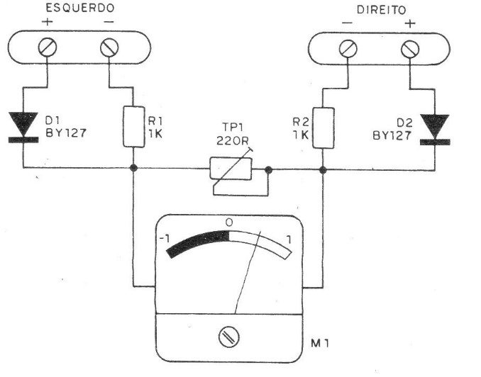
With this circuit it is possible to have a safe indication of the balance point for the signals of the two channels of a stereo system. A milliammeter with zero in the center of the scale (1-0-1 mA) is used as the basis for this project, which in the balance should indicate a zero current (0). The resistors R1 and R2 have their value determined by the power of the stereo with which the meter must be used. For devices up to 5 W these resistors can be 470 R; for devices up to 20 W these must have 1k and for more than 20 W, 500 ohms are added for each 10 W. Diodes D1 and D2 can be silicon for general use such as 1N4004, 1N4007, BY127, etc. Note that this circuit does not use a power supply, as the energy for its operation comes from the stereo with which it works. The TP1 trimpot is used to adjust the device's sensitivity according to the power of your amplifier.