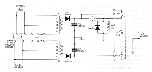
The author of this project, found in a 1982 documentation, says that we in electronics are smart, but today's thieves are much smarter than we might think. And it was with this in mind that the author “came up” with a big surprise for thieves who try to eventually disarm the security system of a residence, turning off their general key. In the figure we have the circuit of the system in question. Two transformers are used with the primary 110 V or 220 V, depending on your network, and 12 V secondary with a current of at least 100 mA, or according to the relay used, or alarm. As additional elements we have two rectifier diodes in each transformer, and filter electrolytics, in addition to a relay, a protection diode for this relay and some switches. The operation of the circuit is as follows: after the installation of the system in the general power supply of the house (normally outside the residence-) is completed CH1 and then press for a moment CH2 (switch of the normally open type). With this procedure, the relay is energized, passing its contacts to the closed position, so the relay is powered by its own contacts and at the same time keeps the alarm system off. If someone switches off the main switch, the transformer T1 is without power, and thus the relay is immediately deactivated, returning its contacts to the initial position. With this, the alarm system starts to receive power from the other transformer (T2) that is connected before the switch. See that the alarm does not stop, even if the key is turned on. To do this, we can turn off the alarm by pressing CH3, or by pressing the CH2 switch for a few moments. The CH1 switch deactivates the alarm system. Electrolytics must have a working voltage of at least 16 V, and rectifier diodes are of type 1N4004 or equivalent.