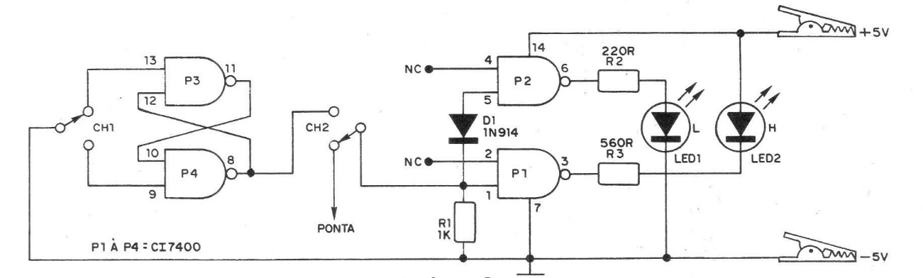
The circuit in question was found in a 1982 documentation. Its operation is as follows: since the circuit is powered with 5 V (which can be removed from the TTL circuit to be analyzed), the two LEDs will remain off, because the inverter formed by the port P1 will have its input at low level, through R1, sending a high level to the LED connected at its output, polarizing it inversely. The input of the P2 inverter connected via diode D1 to the input of P1 does not recognize its initial low level, as there is a voltage drop of approximately 0.7 V in the diode, which added to the drop in R1 keeps the P2 input level high, sending a low level to the output and preventing the LED from turning on. When a low level is sent to the probe (CH2 in A), the input of P2 initially at a high level, goes to a low level, taking the output to a high level and thereby making o1ed light up (the LED connected to the output of P1 will remain off because the entry of P1, in the initial state is below). The reverse occurs in B. The flip-flop RS formed by ports P3 and P4 has one of its outputs connected with the input of the logic level indicator, to the probe, showing through the LEDs to the operator the level of the pulses at the output. The pulses are achieved (free of "noise") by switching CH1 to a position and returning it to the initial state.