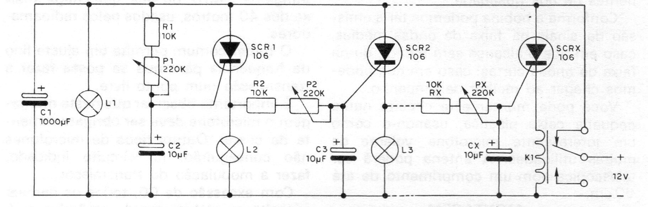
This circuit is from a 1982 documentation. Here we have an adaptation of the circuit already published on this website without the use of an input timer circuit. It is an extensible sequential lighting system, to be used with 12 V continuous power. Readers will be able to use this system in a direction indicator for the car with very attractive effects or in decoration or signage. The operation of this circuit is as follows: when establishing the circuit supply, all SCRs are turned off and, therefore, the relay allows the circulation of a current that immediately makes L1 shine. At the same time, capacitor C2 charges via P1 / R1 to the trigger point of the first SCR. The L2 lamp, with the first SCR driving, lights up a certain time after L1, therefore. The range basically depends on the value of C2 and the setting of P1. With the ignition of L2, the voltage at this point in the circuit rises, and the C3 load is now started via P2 / R2. Again, after a while, SCR2 turns on, making L3 light up.