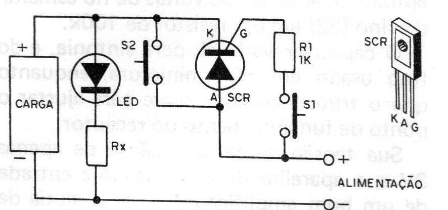
To control direct current loads, under voltages between 12 and 200 V, and currents up to 3 A, we have this interesting circuit, found in a publication in 1981. The base of the circuit is an SCR, type MCR106, TIC106 or IR106, which works like a switch. By pressing S1 momentarily, the SCR turns on, carrying the current to the load circuit, which remains powered until S2 is also momentarily pressed, when then the SCR shuts down. The indicator LED serves to “tell" when the load circuit is receiving power. In applications where the load current is greater than 1A, the SCR must be mounted on a heat radiator. The Rx resistor, connected in series with the LED, has values that depend on the load voltage. For 3 V on the load, the resistor will be 100 ohms and for 48 V, its value will be 4k7. We see that 3 V on the load means 5 V of power, since the SCRs usually have a voltage drop of about 2 V. For this reason, we recommend the circuit for voltages above 12 V., so that the drop is not sensitive in the load, intermediate Rx values can be achieved by a simple proportional calculation. When connecting to the load circuit, it is very important to obey the polarity of the source and the control.