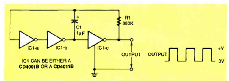
This circuit uses three inverters to generate a rectangular signal whose frequency depends on R1 and C1. The circuit is from a March 1996 Electronics Now.
| Clique na imagem para ampliar |

This circuit uses three inverters to generate a rectangular signal whose frequency depends on R1 and C1. The circuit is from a March 1996 Electronics Now.


