As its name suggests, the reed switch consists of two or more metal blades encapsulated in a glass ampoule, as shown in Figure 1.
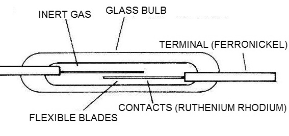
As there is no possibility of having a direct access to the blades, so that we can operate the device, we use an external magnetic field. This magnetic field acts on the induction magnetizing lamps and thereby bend to close the circuit by touching each other or making a commutation in a 3-bladed system, as shown in Figure 2.

In order for us to operate this device with features which allow it to be used with the utmost reliability, all parts of the device must meet certain requirements. Then we start from the blades.
THE BLADES
Evidently, the material with which the blades are made must have ferromagnetic properties, so that they can undergo a momentary magnetization under the action of an external field.
The material used is iron nickel, in a high permeability alloy so that there is no loss of magnetic flux. The magnetic retention should be as small as possible to prevent remaining magnetism from impairing device operation when the external field disappears.
The presence of this retention would cause the contacts to "stick" while the device is on even after the external drive field is removed. The coefficient of expansion of the blades should be equivalent to that of the encapsulation glass to avoid problems during the welding process.
Uneven expansion with heating could result in micro-cracks in the glass which would cause the device's internal gas to leak, which, as we shall see, is of great importance to both the device's performance and its lifetime. The surface of the blades must be completely clean, free of gases which may cause malfunctions.
Finally, the hardness of the iron-nickel alloy must be strictly controlled.
THE GLASS
The glass used in the construction of reed switches must have special characteristics. One of them is the high resistivity, as the blades make internal contact with the bulb and therefore it should work as a perfect insulator.
In the bulbs with reversible systems, there is a small quartz chip between the NO and NC blades, to ensure isolation at this point where there is a close physical proximity between them, as shown in Figure 3.

Obviously, for the same reasons given when speaking of the blades, the glass must have a certain coefficient of expansion. To increase the heat dissipation capacity of the device, iron oxide is added to the glass, which gives it the greenish color which characterizes this type of component.
CONTACTS
Minimal ohmic resistance, flash resistance are some of the requirements for these reed switch elements. These characteristics are the result of rigorously controlled electrolyte baths. The most commonly used material is the rhodium/ruthenium alloy which has a fusion point of approximately 2000°C and has an initial contact resistance that can vary between 50 and 200 milliohms depending on the ampoule type.
The ampoules with rhodium/ruthenium NO contacts switch depending on their size from 10 to 15 watts. For higher power switching up to 100 W with NO contacts, there are tungsten contact ampoules, which have a much higher fusion point of 3387°C, but with higher contact resistances on the order of 500 milliohms.
USE
For operation of a reed switch, we need to make an external magnetic field act on the then bending blades, causing the contacts to occur in the desired ways. We can obtain the external magnetic field in two ways: from a permanent magnet or from a coil, as shown in Figure 4.
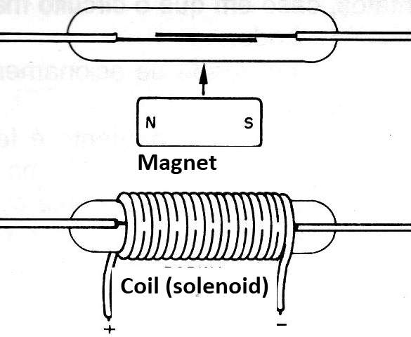
The intensity of the current in the coil and the number of turns determine the intensity of the magnetic field to be produced. In any case, however, we must know the sensitivity of the reed switch, i.e., the intensity of the magnetic field required to drive the device. This sensitivity is usually referred to as A.T. (amp-turn).
The sensitivity of a reed switch is defined during its manufacturing processing and then checked and classified into 5 A.T. Using a standard coil, manufacturers can set the sensitivity of a reed switch as shown in Figure 5.
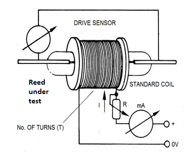
The lower the A.T. value, the more sensitive reed switch will be.
It is important to note that the blades and the terminals form a magnetic circuit, so that the cutting off part of the terminals for the assembly, however small, changes the sensitivity of the reed switch. The breaking stress also varies according to the sensitivity.
In the case of activation by a permanent magnet, the greater the sensitivity of the reed switch, the greater the distance between the bulb and the magnet at the moment of drive or the weaker the magnet used.
APPLICATIONS
For the blades to move towards reed switch operation, there must be a certain positioning of the permanent magnet or the coil. This is necessary for the magnetic field power lines to act on the system in a convenient manner. A change in position causing the magnet or coil to improperly influence the blades causes a loss of sensitivity, i.e., greater approximation or greater "force" of the drive magnet is required for a satisfactory operation as shown in Figure 6.
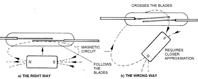
The position for triggering from a permanent magnet also depends on how the reed switch is approached. We then have two possibilities for the bar magnet.
The first is shown in Figure 7 in which the magnet is approached perpendicular to the ampoule, in which case the poles should be oriented parallel to the component.
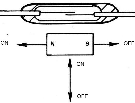
In this case, the created magnetic field closes the magnetic circuit passed by the attracting blades making contact. The second way is shown in Figure 8, and corresponds to a displacement drive parallel to the permanent magnet component, in bar form.
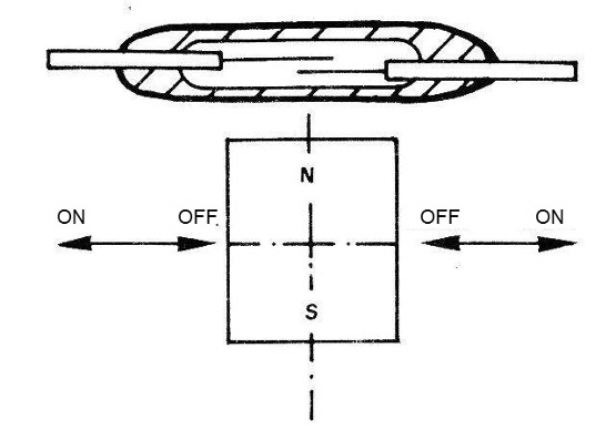
Note that the actuation of one of the poles only on the blades means that in the nearest position we have the reed switch shutdown. We then have two lateral drive positions and a central off position.
It is important to note that this arrangement is exactly what we find in car alarms with magnetic disarming system as it is nowadays. The small bar magnet on the keying is usually misapplied to the reed to achieve disarming, as shown in Figure 9.
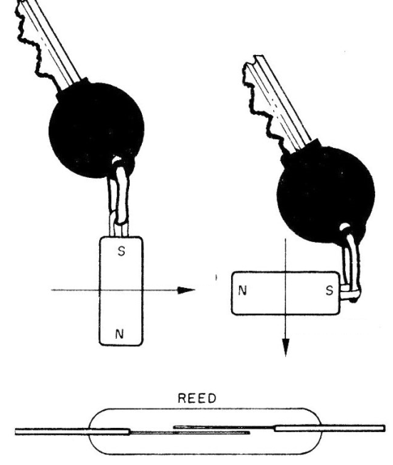
Either we pass the magnet in a lateral motion with the poles vertically, or we approach the magnet with the poles in a line parallel to the reed.
Other important modes of activation can be achieved when we change the shape of the magnet or when couple to devices which can perform the most diverse movements. The fast drive of the reed allows us to generate digital device counting pulses from moving machine parts, final stage elements in machines or even objects passing through certain locations for detection.
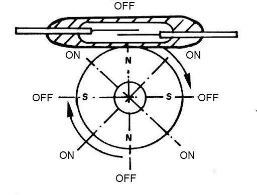
In Figure 10, we have an example of the use for a toroidal or ring-shaped magnet which moves around the reed switch.
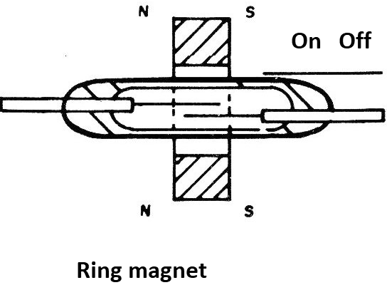
The drive occurs when the ring is directly over the contacts, in which case the magnetic circuit is closed. Another mode of triggering is shown in Figure 11.
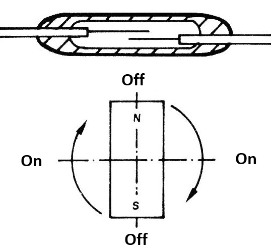
In this case, the triggering is done by the position of a bar magnet which rotates around a certain position, maintaining a constant average distance from the reed switch bulb. This system can serve as the basis for a tachometer since each turn of the magnet produces two drive pulses for an external circuit.
In Figure 12, we have an interesting tachometer circuit which can be used with a reed switch, providing an instrument current proportional to the rotational speed of the magnet.
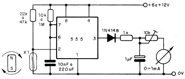
The monostable timing capacitor determines the operating range of the tachometer as well as the series resistor.
A monostable, like the one in Figure 13, provides pulses of constant duration from the rotation of a magnet in the case of a digital drive.
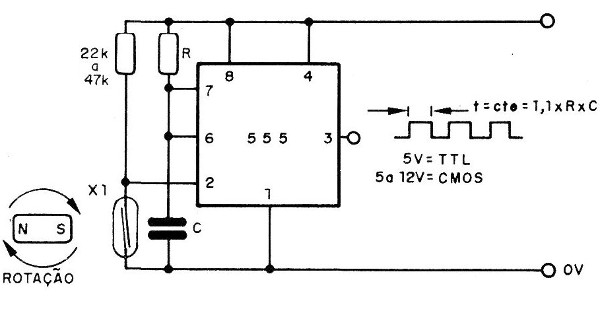
For cases where the rotational speed of the magnet is higher, therefore bar shaped can cause vibration problems, we can use a ring magnet as shown in Figure 14.
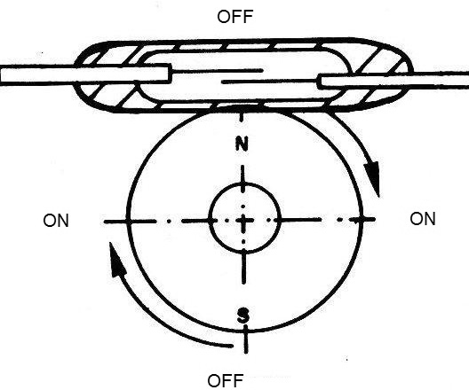
Note that as in the case before each round of the magnet we have the closing and the opening the contacts twice.
A ring magnet or a 4-pole cylinder, as shown in Figure 15, allows 4 pulses to be produced each turn.
A very interesting feature, shown in Figure 16, consists of a converting an NO reed switch (normally open) to an NC reed switch (normally closed).
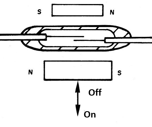
With the drive magnet moving away, the fixed magnet closes the magnetic circuit through the blades, holding them together and thus the contacts closed.
As the drive magnet approaches the pole cancellation position, the magnetic field is neutralized with the opening of the magnetic circuit and consequently of the contacts.
Another interesting drive process is shown in Figure 17.
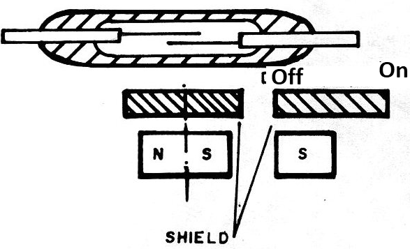
It is the drive through magnetic shielding. A magnetic material that shortens the power lines of the drive magnet magnetic field, when interposed between this magnet and the reed, opens the drive's magnetic circuit, and thus the contacts.
TRIGGERING BY COILS
The triggering of reed switches from coils allows the elaboration of sensitive relays. The main advantage of its use is that if we do not have a ready reed relay that has the desired characteristics it is quite easy to wind up a special coil which meets our needs.
But undoubtedly, another equally important advantage lies in the fact that the enormous sensitivity of the reed switches and the absence of moving parts, other than the blades themselves, allows the elaboration of relays with characteristics that would not be possible with ordinary configurations.
To obtain a reed relay with a simple reed switch NO bulb, simply wrap a coil with the desired drive characteristics around it according to Figure 18.
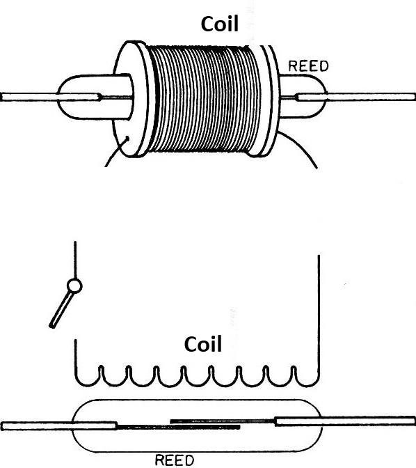
To have a normally closed relay (NC) reed with the NO-type ampoule, just use the configuration in Figure 19.
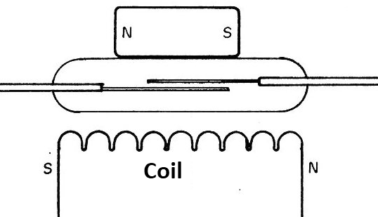
The small permanent magnet built next to the reed switch keeps the magnetic circuit closed and therefore its blades together (closed circuit).
With the magnetic field created by the coil, which must have the right polarity, the field is canceled and the magnetic circuit is interrupted, opening the reed switch contacts. The small permanent magnet can be replaced by a polarization coil, as suggested by the application of Figure 20.
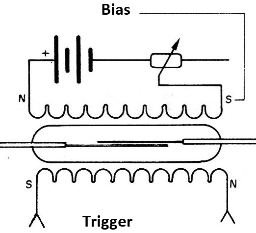
The trimpot P1 acts as a polarization control by determining the sensitivity of the relay.
HANDLING AND USE
The reed switches are delicate components and should be handled with care. A bulb breakage or sealing problems near the terminals can cause inert gas to be lost from inside the device which is responsible for the durability of the contacts and the insulation voltage among other component characteristics.
As we have seen, cutting the terminals alters the sensitivity of the component as it helps to close the magnetic drive circuit.
We should never cut the terminal of a reed directly with pliers. We must fasten it with other pliers and then cut it, the same being indicated in case of bending, as shown in Figure 21.
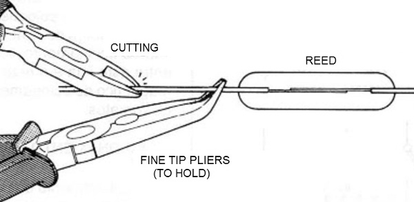
The manufacturer also indicates the minimum length of the cut-off terminal and this factor must be respected when using the component.
With low voltage loads and low currents the reed switch has a lifetime which extends to millions of operations. However, as loads become greater, the component lifetime is reduced. Special care should be taken with capacitive and inductive loads.


