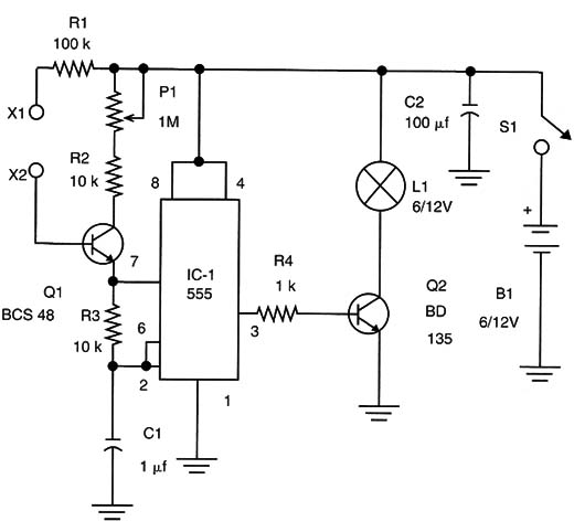
Figure 1 shows visual feedback that can drive a small 6- to 12-volt lamp, much more powerful than the LEDs of the version of BM007E.

This circuit uses a 555 IC configured as an astable multivibrator. The frequency is controlled by the resistance between the positive rail of the power supply and pin 7.
P1 adjusts the basic frequency, and Q1 is used as a variable resistor that changes the resistance according to the amount of current flowing across the base.
Because the base current depends on the resistance between the electrodes (X1 and X2) and the resistance is given by the skin of the subject, it is clear that the frequency at which the lamp flashes depends on the amount of feedback of the person connected between the electrodes.
The circuit is very sensitive due to the presence of the transistor, and even resistances of many megΩ will cause the lamp to flash.
Of course, it is not just people that can be connected to the electrodes. Animals, plants, and even aquariums can be used.
To control the sensitivity, a 4.7 M Ω potentiometer can be wired between the base of Q1 and the 0-volt rail of the circuit. Cl determines the center frequency of the oscillator and can be changed according to the application. The reader is free to experiment with values between 0.1 and 10 ,uF.
The circuit can be powered from cells or a power supply with voltages between 6 and 12 volts. The voltage of the supply will determine the voltage of the lamp. Lamps with currents between 50 and 300 milliamps can be used. If lamps with more than 100 milliamps are used, the transistor Q2 must be mounted on a heatsink. For small lamps (up to 100 milliamps), AA cells can be used.
For higher-power lamps, if cells are used, they must be C or D types.
If a power supply is used, it must include a trans- former. Do not use transformerless power supplies, because they are not isolated from the AC power line and the electrodes could cause severe shock hazards.
The circuit can be mounted using a PCB or a solderless board. The electrodes from the basic project can be used, depending on the application.
A Darlington power transistor, such as the TIP120, can be used, replacing Q2. It is enough to increase R4 to 4,7 ko. This transistor can drive lamps up to 4 lamps from a 12-Volt supply.
Testing and Using
Power on the circuit and observe the lamp. If the electrodes are separated, the lamp will not flash.
Placing your fingers on the two electrodes at the same time and acting on P1, the lamp will flash. You will see that the flash rate will change when you press on the electrodes.
IC1 - 555 integrated circuit
Q1 - BC548 or the equivalent NPN general-purpose silicon transistor
Q2 - BD135 or equivalent NPN medium-power silicon transistor
X1, X2 - Electrodes
L1 - Incandescent lamp, 6 or 12 V, Up to 300 mA
R1 - 100 k Ω x 1/8 W resistor, brown, black, yellow
R2, R3 - 10 kΩ x 1/8 W resistor, brown,black, orange
R4- 1 kΩ,x 1/8 W resistor, brown, black, red
P1- 1 MΩ, potentiometer, lin or log
C1 - 1 µF electrolytic or polyester capacitor (see text)
C2 - 100 ,uF x 12 v electrolytic capacitor
S1- On/off switch
B1 -: 6 or 12 V power supply or cells (see 1text)
Other: PCB or solderless board, cell holder (Optional), plastic box, wires, solder, etc.


