Figure 1 shows the basic circuit and its waveforms. It works as follows:
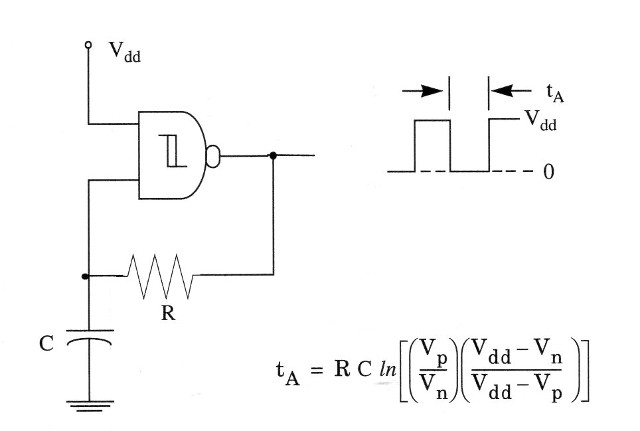
Before power is applied, input and outputs are at the ground potential (0 V, or logic level 0) and capacitor C is discharged. At power on, the output goes to high (Vdd, or logic level 1), and C charges through R until Vp is reached. The output then goes low. C is now discharged through R until Vn is reached. The output then goes high and charges C toward Vp through R. Therefore, we conclude that input alternatively swings between Vp and Vn as the output goes high and low.
An important advantage of this circuit is that the oscillator is self-starting at power on. We also see that the basic oscillator consists of an amplifler (4093 gate) and a feedback network. For oscillation to occur, the gain of the amplifier x attenuation of the feedback network must be greater than 1.
The frequency stability of an oscillator such as this is primarily dependent on the phase-changing properties of the feedback network. For the 4093, we have good performance in frequencies as high as 1 MHz, and the RC network values are given in the figure.
As in the case of inverters, the oscillator can be controlled by one input, allowing the operation as shield. In this case the 4093 must be powered from the microcontroller’s voltage source and the oscillator is enabled by a high (1) logic level at the control input.
Many projects in this book will use this configuration. See item 1.3.8.
Monostable Multivibrator
The monostable multivibrator has one stable state and one unstable state. It remains in the stable state until it is triggered. When triggered, it will be placed temporary in the other state. The multivibrator will remain in that state during a time delay, after which it snaps back to its original condition.
We can use monostable multivibrators to detect leading and trailing edges of waveforms, in medium-accuracy generators, and also in time-delay generators.
Each gate of a 4093 IC can be used as monostable multivibrator. There are several ways to create a monostable multivibrator with the gates as shown in Fig. 2.
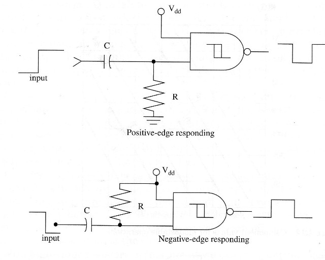
In Fig. 2a, we show a positive-edge responding monostable multivibrator. In this configuration, the output goes to 0 during a definite time delay given by the RC network, and it swings back to 1 when a positive transition occurs in its input.
In Fig. 2b, a negative-edge responding configuration is shown. The output swings from zero to one during a definite time delay when the input voltage falls from one (+Vcc) to zero (0 V).
This circuit can be controlled by microcontrollers acting as a shield in many applications. Resistor values in the RC network can go from 10 k up to 10 M, and the capacitor can range from 50 pF on up.
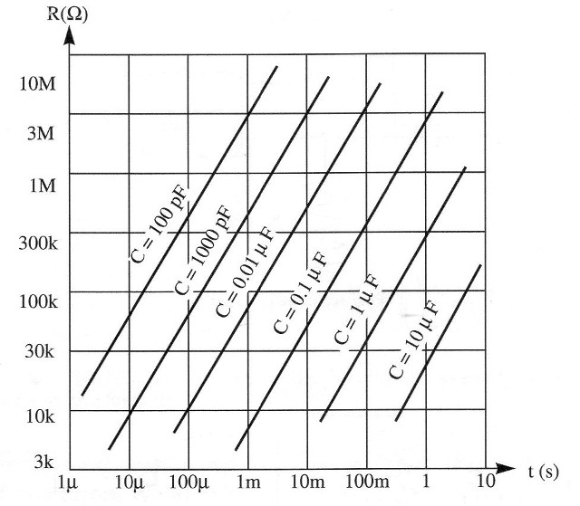
Time delay as function of component values in the RC network is given in the chart shown in Fig. 3. Some usage limits should be observed for this kind of monostable multivibrator:
The input voltage must stay in the post-trigger state for a period of time longer than the on time.
The input transition must be noise free.
The circuit may not be retriggered until after full recovery.
The input must return into the pretrigger state long enough to let the RC network recover fully.
As, really, the circuits shown are edge detectors, they also can be
called half monostable.
Set-Reset Flip-Flop
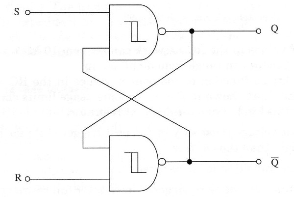
In Fig. 4 we show how two NAND gates of a 4093 can be wired to form a set-reset flip-flop. The circuit is a pulse-triggered flip-flop that needs a negative-moving pulse to be triggered.
This circuit operates as follows.
As we can see, the circuit has two outputs: a normal output, called Q, and a inverted output called Q\. When one output is 1, the other necessarily will be a 0, and vice-versa, because they are complementary.
The circuit has also two inputs named S (set) and R (reset), as shown in the figure, where the trigger signals are applied. R input is wired to Q output, and S input is wired to Q\ output, performing a closed-loop for the digital signals.
When a negative-moving trigger pulse is applied to S input, the output Q swings to the 1 state. As this output is wired to input R, the 1 state causes output Q\ to fall to a 0 level. But Q output is also wired to input S, causing a feedback that causes its output to remain at 1 even after the trigger pulse has disappeared.
To trigger the multivibrator again, changing the output states, we should apply a negative-moving pulse to input R. This pulse causes the output to go 1 and, as this input is wired to input R, the trigger pulse also causes the output Q to go to a 0 level.
A zero in this output Q goes to input S and also, after the trigger pulse disappears, the outputs remain in their states. Note that the circuit has two stable states, and we only can change these states with set or reset (R or S) negative-moving pulses applied to its inputs. A manually triggered flip-flop can be constructed by wiring switches to the set-reset inputs as shown in Fig. 5
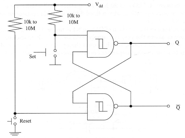
The 4093 high input impedance allows the use of a large range of resistor values in this application. They typically can range from 1 k to 10 M. Resistors are used to apply a high logic level at the inputs when the switches are open.
Without the resistors, we will have an indefinite state at the inputs when the switches are off, and this could cause erratic operation of the circuit. With high-value resistors in this circuit we can get a touch-triggered biestable as shown in Fig. 6.
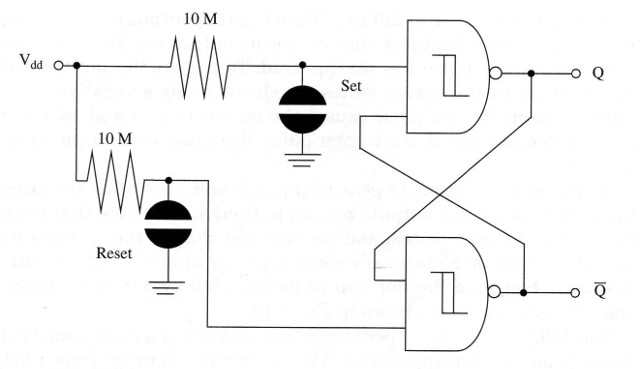
Many projects in this book use that configuration as the starting point. We can obtain different performances for this basic circuit using other gates as inverters and obtain positive-moving biestables.
This circuit can also be used in shield (see previous configurations)


