Here a simple assembly which can be used in various applications such as decorations, toys, robots, and even a bicycle.
The circuit consists of an oscillator that flashes alternately two white power LEDs.
The operation is done with 6V batteries or power supply and the brightness of the LEDs is enough that they are visible from a good distance.
How it works:
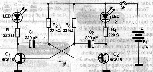
The circuit base is an astable multivibrator with two transistors, a configuration quite explored in electronic design. Each transistor only conducts current for a certain time, determined by the value of C1 and C2.
If we connect an LED to each transistor, they flash alternately at regular intervals which will depend on precisely the values of these capacitors. The values indicated in the original project are 220 µF, but the reader can experiment with values between 47 µF and 470 µF for both C1 and C2.
Even the resistors R2 and R3 are not critical. Depending on the transistors used, if 'hard' to oscillate the reader can experiment by changing values for R2 and R3 in the range of 15 K Ω to 56 K Ω.
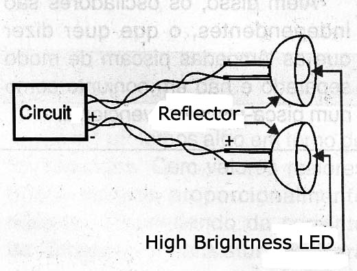
The white LEDs are high power, which can be fitted by some distance from the device. In Figure 1 we have an installation suggestion.

In Figure 2 we have the complete diagram of the device.

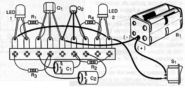
In figure 3 we made a mounting using a terminal strip. This strip, with the other components can be installed in a plastic box. Only the wires for the LEDs leave the box.

In the assembly carefully observe the polarity of the LEDs, as if reversed the device does not work.
Completing the assembly is only connect the appliance. The LEDs should flash alternately when we power the unit. If any LED is not lit, make sure it is not reversed.
If there is no blink, check the connection of transistors. If the flashes are too slow or fast, change C1 and C2. Proven operation is only to install.
Q1, Q2 - BC548 – NPN general purpose transistors NPN
C1, C2 - 220 µF x 12 V - Electrolytic Capacitors
LED1 and LED2 - high-power white LEDs
S1 - SPST switch
B1 - 4 small batteries or medium (or source)
R1, R4 - 220 Ω x 1/8 W - resistors - red, red, brown
R2, R3 - 22 k Ω x 1/8 W - resistors - red, red, orange
Miscellaneous:
Terminal strip, battery holder, box for mounting, wires, weld, etc.


