
The circuit shown in figure 1 is an unusual solution for a bargraph that triggers a relay when the input voltage exceeds a value programmed by the reference voltage divider.
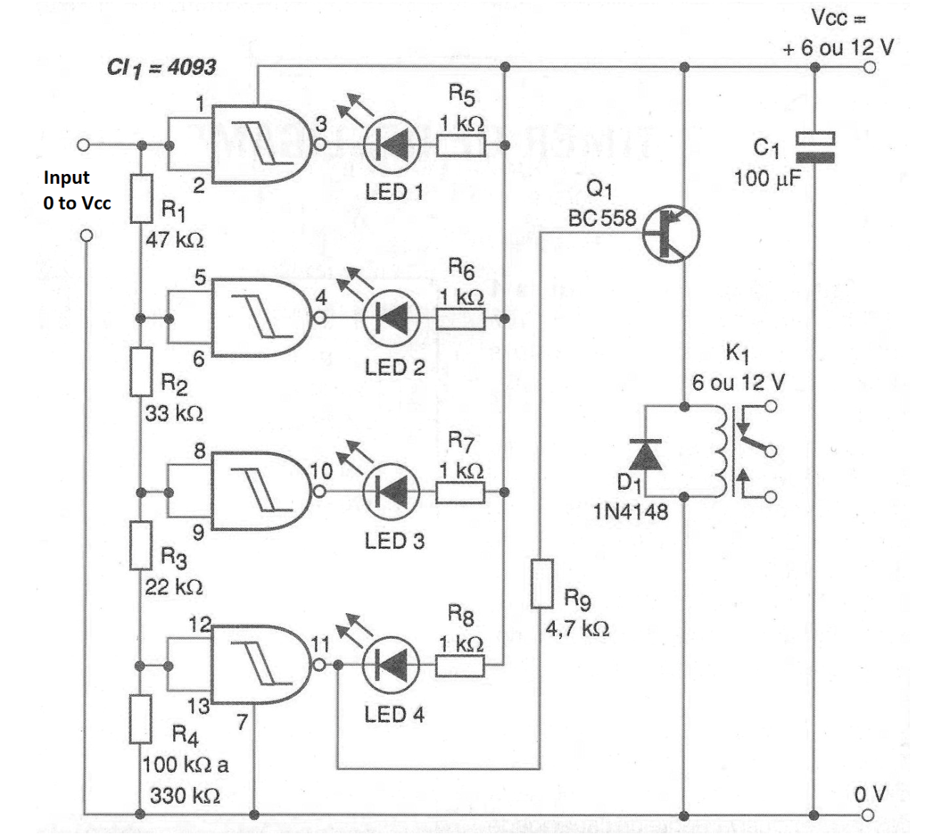
The circuit can be used to trigger an alarm or disable a machine when the input voltage exceeds a certain value. With the addition of a trip circuit on the first LED, we can also cause a second relay to be tripped in the event of an undervoltage.
The drive voltages of each of the 4 LEDs are programmed by the resistive divider formed at the 4093 NAND gate inputs that function as comparators. The indicated values provide a logarithmic scale within a range of narrow input voltages.
The relay depends exclusively on the type of load to be controlled and the circuit can be supplied with voltages from 6 to 12 V. In figure 2 we have the printed circuit board for this application assuming the use of discrete LEDs and a relay with DIL base for socket mounting.
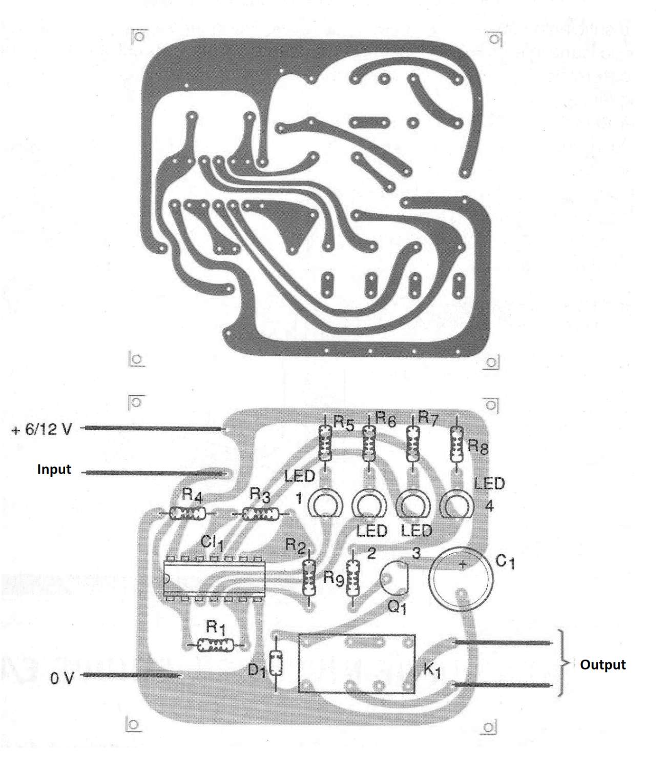
The design can be changed to use 4 LED bars and other types of relays. With the addition of an RC network at the input the circuit can be transformed into a timer with sequential status monitoring by the LEDs.
MATERIAL LIST
CI-1 - 4093 - CMOS integrated circuit
Q1 - BC558 or equivalent - general purpose PNP transistor
LED1 to LED4 - Common red LEDs
D1 - 1N4148 - general purpose diode
R1 - 47 k ohm x 1/8 W - resistor - yellow, violet, orange
R2 - 33 k ohm x 1/8 W - resistor - orange, orange, orange
R3 - 22k ohm x 1/8 W - resistor - red, red, orange
R4 - 100 k ohm at 330 k ohm x 1/8 W - resistor
R5 to R8 - 1k ohm x 1/8 W - resistors - brown, black, red
R9 - 4.7 k ohm x 1/8 W - resistor - yellow, violet, red
K1 - 6 or 12 V x 50 mA or more sensitive - relay
C1 - 100 uF x 16 V - electrolytic capacitor
Several:
Printed circuit board, relay socket, wires, solder, etc.


