
This is an experimental radio for the medium wave range, which with a small antenna can easily pick up the strongest local stations. With larger antenna the weaker stations can also be heard in a loudspeaker or phone. The few components used make this assembly ideal for the beginner.
This radio is suitable for beginners and students who want a simple model with few components for local mid-wave stations.
Despite the simplicity, the strongest stations produce good sound on the speaker.
The power supply can be made with voltages from 1.5 to 6 V, which means from 1 to 4 cells, and current consumption is quite low.
Grounding is important for weaker stations, which can be done in a buried metal bar, in the water pipe, in the neutral pole of the outlet, in any large metal object in contact with the ground or even holding between the fingers the tip of the wire connected to T.
ASSEMBLY
In figure 1 we have the complete diagram of the radio.
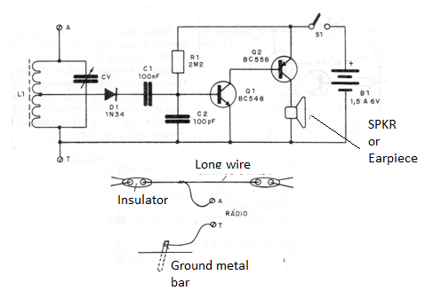
The coil is wound on a ferrite rod of 0.8 to 1 cm in diameter and 10 to 25 cm in length. We can use enameled wire of any thickness between the numbers 18 and 28 or even ordinary stranded wire. We wind 50 turns where we make a tap (tap) and then another 30 turns finishing the coil.
CV can be a miniature variable transistorized radio disassembled or the big type harnessed from an old valve radio. Diode D1 is Germanium of any type and all capacitors can be ceramic or polyester.
The loudspeaker can either be 4 or 8 ohm, as can also use a headset or earpiece from 4 to 200 ohm without problems. The resistor R1 determines the sensitivity of the circuit and can be changed in the range of 1M to 4M7. Look for the best value that gives the loudest sound without distortion.
TEST AND USE
To prove it is only to connect the batteries, antenna and earth and seek to tune the stronger local stations. Do not be surprised if the strongest stations "spread" a little, this is a characteristic of this radio.
Higher selectivity can be obtained by reducing winding turns of 30. However, with this procedure we also decreased sensitivity.
If there is no adequate coverage of the range, it is a sign that the variable employed has a small capacitance. See if you are not using a variable of few FM cards that has lower maximum capacitance.
MATERIAL LIST
Q1 - BC548 or equivalent - NPN general purpose transistor
Q2 - BC558 or equivalent - general purpose PNP transistor
D1 - 1N34 or any other germanium diode
L1 - see text
CV - variable - see text
FTE - low impedance speaker or handset
S1 – On-Off switch
B1 - 1 to 4 small batteries
R1 - 2M2 - resistor (red, red, green)
C1 - 100 nF - ceramic or polyester capacitor
C2 - 100 nF - ceramic capacitor
Miscellaneous: printed circuit board, ferrite stick, battery hold


